STRING DATA TRANSFERS
There are five string data transfer instructions: LODS, STOS, MOVS, INS, and OUTS. Each string instruction allows data transfers that are either a single byte, word, or doubleword (or if repeated, a block of bytes, words, or doublewords). Before the string instructions are presented, the operation of the D flag-bit (direction), DI, and SI must be understood as they apply to the string instructions. In the 64-bit mode of the Pentium 4 and Core2, quadwords are also used with the string instructions such as LODSQ.
The Direction Flag
The direction flag (D, located in the flag register) selects the auto-increment 1D = 02 or the auto-decrement 1D = 12 operation for the DI and SI registers during string operations. The direction flag is used only with the string instructions. The CLD instruction clears the D flag 1D = 02 and the STD instruction sets it 1D = 12. Therefore, the CLD instruction selects the auto-increment mode 1D = 02 and STD selects the auto-decrement mode 1D = 12.
Whenever a string instruction transfers a byte, the contents of DI and/or SI are incremented or decremented by 1. If a word is transferred, the contents of DI and/or SI are incremented or decremented by 2. Doubleword transfers cause DI and/or SI to increment or decrement by 4. Only the actual registers used by the string instruction are incremented or decremented. For example, the STOSB instruction uses the DI register to address a memory location. When STOSB executes, only the DI register is incremented or decremented without affecting SI. The same is true of the LODSB instruction, which uses the SI register to address memory data. A LODSB instruction will only increment or decrement SI without affecting DI.
DI and SI
During the execution of a string instruction, memory accesses occur through either or both of the DI and SI registers. The DI offset address accesses data in the extra segment for all string instructions that use it. The SI offset address accesses data, by default, in the data segment. The segment assignment of SI may be changed with a segment override prefix, as described later in this chapter. The DI segment assignment is always in the extra segment when a string instruction executes. This assignment cannot be changed. The reason that one pointer addresses data in the extra segment and the other in the data segment is so that the MOVS instruction can move 64K bytes of data from one segment of memory to another.
When operating in the 32-bit mode in the 80386 microprocessor or above, the EDI and ESI registers are used in place of DI and SI. This allows string using any memory location in the entire 4G-byte protected mode address space of the microprocessor.
LODS
The LODS instruction loads AL, AX, or EAX with data stored at the data segment offset address indexed by the SI register. (Note that only the 80386 and above use EAX.) After loading AL with
a byte, AX with a word, or EAX with a doubleword, the contents of SI increment, if D = 0 or decrement, if D = 1. A 1 is added to or subtracted from SI for a byte-sized LODS, a 2 is added or subtracted for a word-sized LODS, and a 4 is added or subtracted for a doubleword-sized LODS. Table 4–11 lists the permissible forms of the LODS instruction. The LODSB (loads a byte) instruction causes a byte to be loaded into AL, the LODSW (loads a word) instruction causes a word to be loaded into AX, and the LODSD (loads a doubleword) instruction causes a double- word to be loaded into EAX. Although rare, as an alternative to LODSB, LODSW, LODSD, and LODSQ, the LODS instruction may be followed by a byte-, word- or doubleword-sized operand to select a byte, word, or doubleword transfer. Operands are often defined as bytes with DB, as words with DW, and as doublewords with DD. The DB pseudo-operation defines byte(s), the DW pseudo-operation defines word(s), and the DD pseudo-operations define doubleword(s).
Figure 4–18 shows the effect of executing the LODSW instruction if the D flag 0, SI 1000H, and DS 1000H. Here, a 16-bit number stored at memory locations 11000H and 1l001H moves into AX. Because D 0 and this is a word transfer, the contents of SI incre- ment by 2 after AX loads with memory data.
STOS
The STOS instruction stores AL, AX, or EAX at the extra segment memory location addressed by the DI register. (Note that only the 80386–Core2 use EAX and doublewords.) Table 4–12 lists all forms of the STOS instruction. As with LODS, a STOS instruction may be appended with a B, W, or D for byte, word, or doubleword transfers. The STOSB (stores a byte) instruction stores the byte in AL at the extra segment memory location addressed by DI. The STOSW (stores a word) instruction stores AX in the extra segment memory location addressed by DI. A doubleword is stored in the extra segment location addressed by DI with the STOSD (stores a doubleword) instruction. After the byte (AL), word (AX), or doubleword (EAX) is stored, the contents of DI increment or decrement.
STOS with a REP. The repeat prefix (REP) is added to any string data transfer instruction, except the LODS instruction. It doesn’t make any sense to perform a repeated LODS operation. The REP prefix causes CX to decrement by 1 each time the string instruction executes. After CX decrements, the string instruction repeats. If CX reaches a value of 0, the instruction terminates and the program continues with the next sequential instruction. Thus, if CX is loaded with 100 and a REP STOSB instruction executes, the microprocessor automatically repeats the STOSB instruction 100 times. Because the DI register is automatically incremented or decremented after each datum is stored, this instruction stores the contents of AL in a block of memory instead of a single byte of memory. In the Pentium 4 operated in 64-bit mode, the RCX register is used with the REP prefix.
Suppose that the STOSW instruction is used to clear an area of memory called Buffer using a count called Count and the program is to function call ClearBuffer in the C+ + envi- ronment using the inline assembler. (See Example 4–5.) Note that both the Count and Buffer address are transferred to the function. The REP STOSW instruction clears the memory buffer called Buffer. Notice that Buffer is a pointer to the actual buffer that is cleared by this function.
MOVS
One of the more useful string data transfer instructions is MOVS, because it transfers data from one memory location to another. This is the only memory-to-memory transfer allowed in the 8086–Pentium 4 microprocessors. The MOVS instruction transfers a byte, word, or doubleword from the data segment location addressed by SI to the extra segment location addressed by SI. As with the other string instructions, the pointers then are incremented or decremented, as dictated by the direction flag. Table 4–14 lists all the permissible forms of the MOVS instruction. Note that only the source operand (SI), located in the data segment, may be overridden so that another segment may be used. The destination operand (DI) must always be located in the extra segment.
It is often necessary to transfer the contents of one area of memory to another. Suppose that we have two blocks of doubleword memory, blockA and blockB, and we need to copy blockA into blockB. This can be accomplished using the MOVSD instruction as illustrated in Example 4–6, which is a C+ + language function written using the inline assembler. The function receives three pieces of information from the caller: blockSize and the addresses of blockA and blockB. Note that all data are in the data segment in a Visual C+ + program so we need to copy DS into ES, which is done using a PUSH DS followed by a POP ES. We also need to save all registers that we changed except for EAX, EBX, ECX, and EDX.
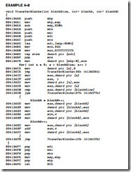
Example 4–7 shows the same function written in C+ + exclusively, so the two methods can be compared and contrasted. Example 4–8 shows the assembly language version of
Example 4–7 for comparison to Example 4–6. Notice how much shorter the assembly language version is compared to the C+ + version generated in Example 4–8. Admittedly the C+ + version is a little easier to type, but if execution speed is important, Example 4–6 will run much faster than Example 4–7.
The INS (input string) instruction (not available on the 8086/8088 microprocessors) transfers a byte, word, or doubleword of data from an I/O device into the extra segment memory location addressed by the DI register. The I/O address is contained in the DX register. This instruction is useful for inputting a block of data from an external I/O device directly into the memory. One application transfers data from a disk drive to memory. Disk drives are often considered and interfaced as I/O devices in a computer system.
As with the prior string instructions, there are three basic forms of the INS. The INSB instruction inputs data from an 8-bit I/O device and stores it in the byte-sized memory location indexed by SI. The INSW instruction inputs 16-bit I/O data and stores it in a word-sized memory location. The INSD instruction inputs a doubleword. These instructions can be repeated using the REP prefix, which allows an entire block of input data to be stored in the memory from an I/O device. Table 4–15 lists the various forms of the INS instruction. Note that in the 64-bit mode there is no 64-bit input, but the memory address is 64 bits and located in RDI for the INS instructions.
Example 4–9 shows a sequence of instructions that inputs 50 bytes of data from an I/O device whose address is 03ACH and stores the data in extra segment memory array LISTS. This software assumes that data are available from the I/O device at all times. Otherwise, the software must check to see if the I/O device is ready to transfer data precluding the use of a REP prefix.
OUTS
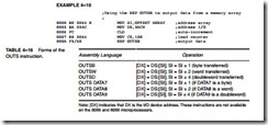
The OUTS (output string) instruction (not available on the 8086/8088 microprocessors) transfers a byte, word, or doubleword of data from the data segment memory location address by SI to an I/O device. The I/O device is addressed by the DX register as it is with the INS instruction. Table 4–16 shows the variations available for the OUTS instruction. In the 64-bit mode for the Pentium 4 and Core2, there is no 64-bit output, but the address in RSI is 64 bits wide.
Example 4–10 shows a short sequence of instructions that transfer data from a data segment memory array (ARRAY) to an I/O device at I/O address 3ACH. This software assumes that the I/O device is always ready for data.


