Module 1: learning unit 3
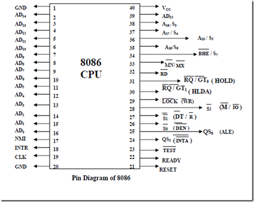
•It is a 16-bit µp.
•8086 has a 20 bit address bus can access up to 220 memory locations (1 MB).
•It can support up to 64K I/O ports.
•It provides 14, 16 -bit registers.
•It has multiplexed address and data bus AD0- AD15 and A16 – A19.
•It requires single phase clock with 33% duty cycle to provide internal timing.
•8086 is designed to operate in two modes, Minimum and Maximum.
•It can prefetches upto 6 instruction bytes from memory and queues them in order to speed up instruction execution.
•It requires +5V power supply.
•A 40 pin dual in line package
Minimum and Maximum Modes:
•The minimum mode is selected by applying logic 1 to the MN / MX input pin. This is a single microprocessor configuration.
•The maximum mode is selected by applying logic 0 to the MN / MX input pin. This is a multi micro processors configuration.
Block Diagram of 8086
Internal Architecture of 8086
•8086 has two blocks BIU and EU.
•The BIU performs all bus operations such as instruction fetching, reading and writing operands for memory and calculating the addresses of the memory operands. The instruction bytes are transferred to the instruction queue.
•EU executes instructions from the instruction system byte queue.
•Both units operate asynchronously to give the 8086 an overlapping instruction fetch and execution mechanism which is called as Pipelining. This results in efficient use of the system bus and system performance.
•BIU contains Instruction queue, Segment registers, Instruction pointer, Address adder.
•EU contains Control circuitry, Instruction decoder, ALU, Pointer and Index register, Flag register.
BUS INTERFACR UNIT:
•It provides a full 16 bit bidirectional data bus and 20 bit address bus.
•The bus interface unit is responsible for performing all external bus operations.
Specifically it has the following functions:
•Instruction fetch, Instruction queuing, Operand fetch and storage, Address relocation and Bus control.
•The BIU uses a mechanism known as an instruction stream queue to implement a
pipeline architecture.
•This queue permits prefetch of up to six bytes of instruction code. When ever the queue of the BIU is not full, it has room for at least two more bytes and at the same time the EU
is not requesting it to read or write operands from memory, the BIU is free to look ahead in the program by prefetching the next sequential instruction.
•These prefetching instructions are held in its FIFO queue. With its 16 bit data bus, the BIU fetches two instruction bytes in a single memory cycle.
•After a byte is loaded at the input end of the queue, it automatically shifts up through the FIFO to the empty location nearest the output.
•The EU accesses the queue from the output end. It reads one instruction byte after the other from the output of the queue. If the queue is full and the EU is not requesting access to operand in memory.
•These intervals of no bus activity, which may occur between bus cycles are known as
Idle state.
•If the BIU is already in the process of fetching an instruction when the EU request it to read or write operands from memory or I/O, the BIU first completes the instruction fetch bus cycle before initiating the operand read / write cycle.
•The BIU also contains a dedicated adder which is used to generate the 20bit physical address that is output on the address bus. This address is formed by adding an appended 16 bit segment address and a 16 bit offset address.
•For example: The physical address of the next instruction to be fetched is formed by combining the current contents of the code segment CS register and the current contents of the instruction pointer IP register.
•The BIU is also responsible for generating bus control signals such as those for memory read or write and I/O read or write.
EXECUTION UNIT
The Execution unit is responsible for decoding and executing all instructions.
•The EU extracts instructions from the top of the queue in the BIU, decodes them, generates operands if necessary, passes them to the BIU and requests it to perform the read or write bys cycles to memory or I/O and perform the operation specified by the instruction on the operands.
•During the execution of the instruction, the EU tests the status and control flags and updates them based on the results of executing the instruction.
•If the queue is empty, the EU waits for the next instruction byte to be fetched and shifted to top of the queue.
•When the EU executes a branch or jump instruction, it transfers control to a location corresponding to another set of sequential instructions.
•Whenever this happens, the BIU automatically resets the queue and then begins to fetch instructions from this new location to refill the queue.

![image_thumb[1] image_thumb[1]](http://lh5.ggpht.com/-e7NYtHXO2p0/VNZZ8u10FWI/AAAAAAABLes/1PCAv4IrjVs/image_thumb%25255B1%25255D_thumb.png?imgmax=800)
![image_thumb[2] image_thumb[2]](http://lh6.ggpht.com/-8cjX5rqFemw/VNZaBQFGBII/AAAAAAABLe8/6l2QBfqPh1w/image_thumb%25255B2%25255D_thumb.png?imgmax=800)