Serial Data Transmission
The hallmark of contemporary industrial computing is the linking together of multiple processors to form a "local area network" or LAN. The degree of complexity of the LAN may be as simple as a microcontroller interchanging data with an I/O device, as complicated as linking multiple processors in an automated robotic manufacturing cell, or as truly complex as the linking of many computers in a very high speed, distributed system with shared disk and 110 resources.
All of these levels of increasing sophistication have one feature in common: the need to send and receive data from one location to another. The most cost-effective way to meet this need is to send the data as a serial stream of bits in order to reduce the cost (and bulk) of multiple conductor cable. Optical fiber bundles, which are physically small, can be used for parallel data transmission. However, the cost incurred for the fibers, the terminations, and the optical interface to the computer currenT1y prohibit optical fiber use, except in those cases where speed is more important than economics.
So pervasive is serial data transmission that special integrated circuits, dedicated solely to serial data transmission and reception, appeared commercially in the early 1970s. These chips, commonly cal LED "universal asynchronous receiver transmitters," or UARTS, perform all the serial data transmission and reception liming tasks of the most popular data communication scheme still in use today: serial 8-bil ASCII coded characters al pre-
defined bit rates of 300 to 19200 bits per second. ‘
Asynchronous transmission utilizes a start bit and one or more stop bits, as shown in Figure 7 .9, to ALERT the receiving unit that a character is about lo arrive and lo signal the end of a character. This "overhead" of extra bits, with the attendant slowing of data byte rates, has encouraged the development of synchronous data transmission schemes. Synchronous data transmission involves alerting the receiving unit to the arrival of data
by a unique pattern that starts data transmission, followed by a long string of characters. The end of transmission is sign ALED by another unique pattern, usually containing error checking characters.
Each scheme has its advantages. For relatively short or infrequent messages, the asynchronous mode is best; for long messages or constant data transmission, the synchronous mode is superior.
The 8051 contains serial data transmission/receiver circuitry that can be programmed to use four asynchronous data communication modes numbered from 0 to 3. One of these, mode I, is the standard UART mode, and three simple asynchronous communication programs using this mode will be developed here. More complicated asynchronous programs that use all of the communication modes will be written in Chapter 9.
Character Transmission Using a Time Delay
Often data transmission is unidirectional from the microcontroller to an output device, such as a display or a printer. Each character sent to the output device takes from 33.3 to .5 milliseconds to transmit, depending upon the baud rate chosen. The program must wait until one character is sent before loading the next, or data will be lost. A simple way to prevent data loss is to use a time delay that delays the known transmission time of one character before the next is sent.
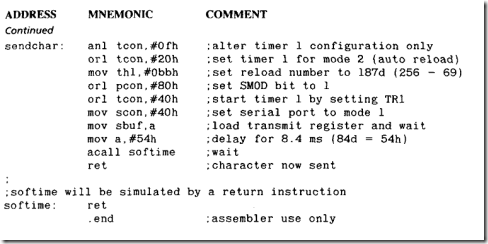
Sendchar
A program cal LED "Send char" takes the character in the A register, transmits it, delays for the transmission time, and then returns to the calling program. Timer I must be used to set the baud rate, which is 1200 baud in this example. The delay for one ten-bit character is 1000/120 or 8.4 milliseconds. The software delay developed in Section 7.5 is used for the delay with the basic delay period of I milliseconds changed to . I milliseconds by redefining "delay." Timer I needs to generate a final baud rate of 1200 at SBUF. Using a 16 megahertz crystal, the reload number is 256 – 16E6/(16 x 12 x 1200), which is 186.6 or integer 187. This yields an actual rate of 1208.
COMMENT
1f timer 1 and the serial port have different uses in the user program, then push and pop affected control registers. But remember, T1 and SBUF can only be used for one function at any given time.
The use of the .set statement lets the user change the basic delay interval to different values in the same program.
The 16 megahertz crystal does not yield convenient standard baud rates of 300, 1200, 2400, 4800, 9600, or 19200. The errors using this crystal for these rates are given in the following table:
|
RATE |
ERROR(%) |
|
300 |
.08 |
|
1200 |
.64 |
|
4800 |
2.12 |
|
9600 |
3.55 |
|
19200 |
8.51 |
The error grows for higher baud rates as ever smaller reload numbers are rounded to the nearest integer. Using an 11.059 megahertz crystal reduces the errors to less than . 002 percent at the cost of speed of program execution.
Character Transmission by Polling
An alternative to waiting a set time for transmission is to monitor the TI flag in the SCON register until it is set by the transmission of the last character written to SBUF. The polling routine must reset T1 before returning to the call program. Failure to reset TI will inhibit all calls after the first, stopping all data transmission except the first character.
This technique has the advantage of simplicity; less code is used, and the routine does not care what the actual baud rate is. In this example, it is assumed that the timer I baud rate has been established at the beginning of the program in a manner similar to that used in the previous example.
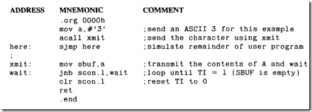
Xmit
The subroutine "Kmit" polls the TI flag in the SCON register to determine when SBUF is ready for the next character. The calling part of the user program follows:
COMMENT
T1 remains a 0 until SBUF is empty; when the 8051 is reset, or upon power up, T1 is set to 0.
Interrupt-Driven Character Transmission
The third method of determining when transmission is finished is to use the interrupt structure of the 8051. One interrupt vector address in program code, location 0023h. is assigned to both the transmit interrupt, T1, and the receive interrupt, RI. When a serial interrupt occurs, a hardware call to location 0023h accesses the interrupt handling routine placed there by the programmer.
The user program "calls" the subroutine by loading the character to be sent into SBUF and enabling the serial interrupt bit in the EI register. The user program can then continue executing. When SBUF becomes empty, T1 will be set, resulting in an immediate vector to 0023h and the subroutine placed there executed. The subroutine at 0023h, calLED "serial," will reset T1 and then return to the user program at the place where it was interrupted.
This scheme is satisfactory for testing the microprocessor when only one character is sent from the program. Long strings of character transmission will overload SBUF. Chapter 9 contains routines that will build on this technique and send arbitrarily long strings with no loss of data.
SBUFR
An interrupt-driven data transmission routine for one character which is assemb LED at the interrupt vector location 0023h. A portion of the user program that activates the interrupt routine is shown.
COMMENT
lf T1 is not cleared before the RETI instruction is used, there will be an immediate interrupt and vector back to 0023h.
RETI is used to reset the entire interrupt structure, not to clear any interrupt bits.
Receiving Serial Data
Transmissions from outside sources to the 8051 are not predictable unless an elaborate time-of-day clock is maintained at the sender and receiver. Messages can then be sent at predefined times. A time-of-day clock generally ties up timers at both ends to generate the required "wake-up" calls.
Two methods are normally used to alert the receiving program that serial data has arrived: software polling or interrupt driven. The sending entity, or "talker," transmits data at random times, but uses an agreed-upon baud rate and data transmission mode. The receiving unit, commonly dubbed the "listener," configures the serial port to the mode and baud rate to be used and then proceeds with its program.
If one programmer were responsible for the talker and another for the listener, lively discussions would ensue when the units are connected and data interchange does not take place. One common method used to test communication programs is for each programmer to use a terminal to simulate the other unit. When the units are connected for the final test, a CRT terminal in a transparent mode, which shows all data transmitted in both directions, is connected between the two systems to show what is taking place in the communication link.
Polling for Received Data
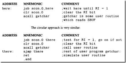
Polling involves periodically testing the received data flag RI and calling the data receiving subroutine when it is set. Care must be taken to remember to reset RI, or the same character will be read again. Reading SBUF does not clear the data in SBUF or the RI flag.
The program can sit in a l00p, constanT1y testing the flag until data is received, or run through the entire program in a circular manner, testing the Hag on each circuit of the program. The l00p approach guarantees that the data be read as s00n as it is received; however, very litT1e else will be accomplished by the program while waiting for the data. The circular approach lets the program run while awaiting the data.
In order not to miss any data, the circular approach requires that the program be able to run a complete circuit in the time it takes to receive one data character. The time restraint on the program is not as stringent a requirement as it may first appear. The receiver is double buffered, which lets the reception of a second character begin while a previous character remains unread in SBUF. If the first character is read before the last bit of the second is complete, then no data will be lost. This means that, after a two-character burst, the program still must finish in one-character time to catch a third.
The character time is the number of bits per character divided by the baud rate. For serial data transmission mode 1, a character uses ten bits: start, eight code bits, and stop. A 1200 baud rate, which might be typical for a system where the talker and listener do not interchange volumes of data, results in a character rate of 120 characters per second, or a character time of 8.33 milliseconds. Using an average of 18 oscillator periods per instruction, each instruction will require 1.13 microseconds to execute, enabling a program length of 7371 instructions. This large machine language program will suffice for many simple control and monitoring applications where data transmission rates are low. If more time is needed, the baud rate could be reduced to as low as 300 baud, yielding a program size of over 29K bytes, which approaches half the maximum size of the ROM in our example 8051 design.
The polling program for the l00p approach follows:
Interrupt-Driven Data Reception
When large volumes of data must be received, the data rate will overwhelm the polling approach unless the user program is extremely short, a feature not usually found in systems in which large amounts of data are interchanged. Interrupt-driven systems allow the program to run with brief pauses to read the received data. In Chapter 9, a program is developed that allows for the reception of long strings of data in a manner completely transparent to the user program.
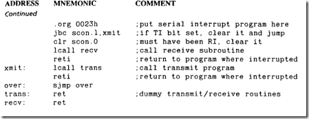
lntdat
This interrupt-driven data reception subroutine assembles the program at 0023h, which is the serial interrupt vector location.
COMMENT
If both RI and T1 are set, this routine will service the transmit function first. After the RETI, which follows the LCALL to trans, the RI bit will still be set, causing an immediate interrupt back to location 0023h where the receive routine will be calLED.
If the transmit or receive subroutines that are calLED take longer to execute than the character time, then data will be lost. Long subroutine times would be highly unusual; however, it is possible to overload any system by constant data reception.
Summary of
An 8051 based microprocessor system has been designed that incorporates many features found in commercial designs. The design can be easily duplicated by the reader and uses external EPROM and RAM so that test programs may be exercised. Various size memories may be used by the impecunious to reduce system cost.
The design features are
External RAM: 8K to 32K bytes
External ROM: 8K to 64K bytes
I/O ports: 1-8 bit, port 1
|
Other ports: port |
3.0 (RXD) |
|
3.1 (TXD) |
|
|
3.2 (I͞N͞T͞͞0) |
|
|
3.3 (͞I͞N͞T͞I) |
|
|
3.4 (T0) |
|
|
3.5 (T1) |
Crystal: 16 megahertz
Other crystal frequencies may be used to generate convenient timing frequencies. The design can be modified to include a single step capability (see Problem 2).
Methods of adding additional ports to the basic design are discussed and several example circuits that indicate the expansion possibilities of the 8051 are presented.
Programs written to test the design can be used to verify any prototypes that are built by the reader. These tests involve verifying the proper operation of the ROM and RAM connections.
Several programs and subroutines are developed that let the user begin to exercise the 805 I instruction code and hardware capabilities. This code can be run on the simulator or on an actual prototype. These programs cover the most common types found in most applications:
Time delays: software; timer, software pol LED; timer, interrupt driven L00kup Tables: PC base, DPTR base
Serial data communications transmission: time delay, software polled, interrupt driven
Serial data communications reception: software polled, interrupt driven
The foundations laid in this chapter will be built upon by example application programs and hardware configurations found in Chapters 8 and 9.
Problems
1. Determine whether the 8051 can be made to execute a single program instruction (single-stepped) using external circuitry (no software) only.
2. OuT1ine a scheme for single-stepping the 8051 using a combination of hardware and software. (Hint: use an͞ I͞N͞͞T͞X.)
3. While running the EPROM test, it is found that the program cannot jump from 2000h to 4000h successfully. Determine what address line(s) is faulty.
4, Calculate the error for the delay program "Softime" when values of 2d. 10d and 1000d milliseconds are passed in A and B.
5. The program "Softime" has a bug. When A= 00h the delay becomes: (B+ l)d x 256d x delay. Find the bug and fix it without introducing a new bug.
6. Find the shortest and longest delays possible using "Softime" by changing only the equate value of the variable "delay."
7. Give a general description of how you would test any time delay program. (Hint: use a port pin.)
8. In the discussion for the program named "Timer," the statement is made that an accurate I ms delay cannot be done due to the need for a count of 1333.33 using a 16 megahertz clock. Find a way to generate an accurate 60 second delay using T0for the basic delay and some registers to count the T0 overflows.
9. Calculate the shortest and longest delays possible using the program named "Timer" by changing the initial value of T0.
10. Why is there no check for an initial timing value of 0000h in the program named "Hard time "?
11. Write a l00kup table program, using the PC as the base, that finds a one-byte square r00t (to the nearest whole integer) of any number placed in A. For example, the square r00ts of 01 and 02 are both 01, while the r00ts of 03 and 04 are 02. Calculate the first four and last four table values.
12- Write a l00kup table, using the DPTR as the base, that finds a two-byte square r00t of the number in A. The first byte is the integer value of the r00t, and the second byte is the fractional value. For example, the square r00t of 02 is 01 .6Ah. Calculate four first and last table values.
13. Write a l00kup table program that converts the hex number in A (0-F) to its ASC11 equivALEnt.
14. A PC based l00kup table. which contains 256d values. is placed 50h bytes after the MOVC instruction that accesses it. Construct the table, showing where the byte associated with A = 00h is located. Find the largest number which can be placed in A to access the table.
15. Construct a l00kup table program that converts the hex number in A to an equivALEnt BCD number in registers R4 (MSB) and R5 (LSB).
16. Reverse Problem 15 and write a l00kup table program that takes the BCD number in R4 (MSB) and R5 (LSB) and converts it to a hex number in A.
17. Verify the errors listed for the 16 megahertz crystal in the third comment after the program named "Sendchar."
18. Verify the error listed for the 11.059 megahertz crystal in the fourth comment after the program named "Sendchar."
19. Does asynchronous communication between two microprocessors have to be done at standard baud rates? Name one reason why you might wish to use standard rates.
20. Write a test program that will "l00p test" the serial port. The output of the serial port (TXD) is connected to the input (RXD), and the test program is run. Success is indicated by port 1 pin 1 going high.
21. What is the significance of the transmit flag, T1, when it is cleared to O? When set to 1?
22. Using the programmable port of Figure 7 .3, write a program that will configure all ports as outputs, and write a 55h to each.
23. Repeat problem 22 using the memory-mapped programmable port of Figure 7 .4.
