Introduction
Microcontrollers tend to be underutilized in many applications. There are several reasons for this anomaly. Principally, the devices are so inexpensive that it makes litT1e economic sense to try to select an optimal device for each application. A new microcontroller involves the expense of new development software and training for the designers and programmers that could easily cost more than the part savings. Also, some members of the technical community are unfamiliar with the microcontroller due to a dearth of established academic course offerings on the subject. These individuals tend to apply classic eight-bit microprocessor families to problems that are more economically served by a microcontroller. Finally, there is always the pressure to use the latest multibyte processor for marketing reasons or just to keep up with the "state of the art."
The result of this application pattern is that Microcontrollers tend to become obsolete at a slower rate than their CPU cousins. The microcontroller will absorb more eight-bit CPU applications as the economic advantage of using Microcontrollers becomes compelling.
Application examples in a textbook present a picture of use that supports the previously-made claim of underutilization. Limitations on space, time, and the patience of the reader preclude the inclusion of involved, multi-thousand line, real-time examples. We will, instead, l00k at pieces of larger problems, each piece representing a task commonly found in most applications.
One of the best ways to get a "feel" for a new processor is to examine circuits and programs that address easily visualized applications and then to write variations. To assist in this process, we will study in detail the following typical hardware configurations and their accompanying programs:
Keyboards
Displays
Pulse measurements
A/D and D/A Conversions
Multi-source interrupts
The hardware and software are inexorably linked in the examples in this chapter. The choice of the first leads to the programming techniques of the second. The circuit designer should have a good understanding of the software limitations faced by the programmer. The programmer should avoid the temptation of having all the tricky problems handled by the hardware.
Keyboards
The predominant interface between humans and computers is the keyboard. These range in complexity from the "up-down" buttons used for elevators to the personal computer QWERTY layout, with the addition of function keys and numeric keypads. One of the first mass uses for the microcontroller was to interface between the keyboard and the main processor in personal computers. Industrial and commercial applications fall somewhere in between these extremes, using layouts that might feature from six to twenty keys.
The one constant in all keyboard applications is the need to accommodate the human user. Human beings can he irritable. They have litT1e tolerance for machine failure; watch what happens when the product isn’t ejected from the vending machine. Sometimes they are bored, or even hostile, towards the machine. The hardware designer has to select keys that will survive in the intended environment. The programmer must write code that will anticipate and defeat inadvertent and also deliberate attempts by the human to confuse the program. It is very important to give instant feed hack to the user that the key hit has been acknowledged by the program. By the light a light, beep a beep, display the key hit, or whatever, the human user must know that the key has been recognized. Even feedback sometimes is not enough; note the behavior of people at an elevator. Even if the "up" light is lit when we arrive, we will push it again to let the machine know that ‘Tm here too."
Human Factors
The keyboard application program must guard against the following possibilities:
More than one key pressed (simultaneously or released in any sequence)
Key pressed and held
Rapid key press and release
All of these situations can be addressed by hardware or software means; software, which is the most cost effective, is emphasized here.
Key Switch Factors
The universal key characteristic is the ability to bounce: The key contacts vibrate open and close for a number of milliseconds when the key is hit and often when it is released. These rapid pulses are not discernable to the human, hut they last a relative eternity in
the microsecond-dominated life of the microcontroller. Keys may be purchased that do not bounce, keys may be debounced with RS flip-flops, or debounced in software with time delays.
Keyboard Configurations
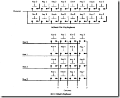
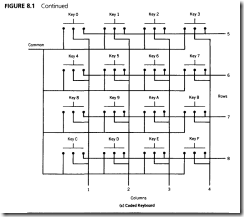
Keyboards are commercially produced in one of the three general hypothetical wiring configurations for a 16-key layout shown in Figure 8. I. The lead-per-key configuration is typically used when there are very few keys to be sensed. Since each key could tie up a port pin, it is suggested that the number be kept to 16 or fewer for this keyboard type. This configuration is the most cost effective for a small number of keys.
The X- Y matrix connections shown in Figure 8. I are very popular when the number of keys exceeds ten. The matrix is most efficient when arranged as a square so that N leads for X and N leads for Y can be used to sense as many as N2 keys. Matrices are the most cost effective for large numbers of keys.
FIGURE 8.1 Hypothetical Keyboard Wiring Configurations
Coded keyboards were evolved originally for telephonic applications involving touchtone signaling. The coding permits multiple key presses to be easily detected. The quality and durability of these keypads are excellent due to the high production volumes and intended use. They are generally limited to 16 keys or fewer, and tend to be the most expensive of all keyboard types.
Programs for Keyboards
Programs that deal with humans via keyboards approach the human and keyswitch factors identified in the following manner:
Bounce: A time delay that is known to exceed the manufacturer’s specification is used to wait out the bounce period in both directions.
Multiple keys: Only patterns that are generated by a valid key pressed are accepted-all others are ignored-and the first valid pattern is accepted.
Key held: Valid key pattern accepted after valid de bounce delay; no additional keys accepted until all keys are seen to be up for a certain period of time.
Rapid key hit: The design is such that the keys are scanned at a rate faster than any human reaction time.
The last item brings up an important point: Should the keyboard be read as the program looks (software polled) or read only when a key has been hit (interrupt driven)?
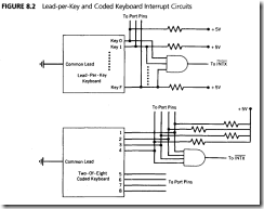
In general, the smaller keyboards (lead-per-key and coded) can be handled either way. The common lead can be grounded and the key pattern read periodically. Or, the lows from each can be active-low ORed, as shown in Figure 8.2, and connected to one of the external͞ I͞N͞T͞X͞ pins.
Matrix keyboards are scanned by bringing each X row low in sequence and detecting a Y column low to identify each key in the matrix. X- Y scanning can be done by using dedicated keyboard scanning circuitry or by using the microcontroller ports under program control. The scanning circuitry adds cost to the system. The programming approach takes processor time, and the possibility exists that response to the user may be sluggish if the program is busy elsewhere when a key is hit. Note how long your personal computer takes to respond to a break key when it is executing a print command, for instance. The choice between adding scanning hardware or program software is decided by how busy the processor is and the volume of entries by the user.
A Scanning Program for Small Keyboards
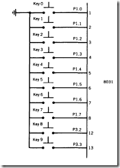
Assume that a lead-per-key keyboard is to be interfaced to the microcontroller. The keyboard has ten keys (0-9), and the de bounce time, when a key is pressed or released, is 20 milliseconds. The keyboard is used to select snacks from a vending machine, so the processor is only occupied when a selection is made. The program constanT1y scans the keyboard waiting for a key to be pressed before calling the vending machine actuator subroutine. The keys are connected to port I (0- 7) and ports 3.2 and 3.3 (8-9), as shown in Figure 8.3.
The 8031 works best when handling data in byte-sized packages. To save internal space, the ten-bit word representing the port pin configuration is converted to a single-byte number.
Because the processor has nothing to do until the key has been detected. the time delay "Softime" (see Chapter 7) is used to de bounce the keys.
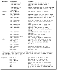
Getkey
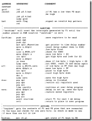
The routine "Getkey " constanT1y scans a ten-key pad via ports 0 and 3. The keys are debounced in both directions and an "all-up" period of 50 milliseconds must be seen before a new key will be accepted. Invalid key patterns (more than one port pin low) are rejected.
FIGURE 8.3 Keyboard Configuration for "Getkey" and "lnkey" Programs
COMMENT
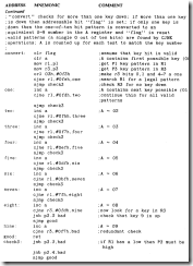
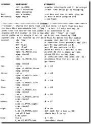
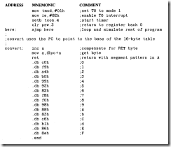
The "convert" subroutine is looking for a single low bit. The CINE patterns all have one bit low and the rest high.
Multiple keys are rejected by "convert." Held keys are ignored as the program waits for a SO d millisecond "all keys up" period before admitting the next key. The program loops so quickly that it is humanly impossible to hit a key so that it can be missed.
The main program is predominanT1y a series of calls to subroutines which can each be written by different programmers. Agreement on what data is passed to and received from the subroutines is essential for success, as well as a clear understanding of what 8051 registers and memory locations are used.
Interrupt-Driven Programs for Small Keyboards
If the application is so time sensitive that the delays associated with debouncing and awaiting an "all-up" cannot be tolerated, then some form of interrupt must be used so that the main program can run unhindered.
A comproM ise may be made by polling the keyboard as the main program looks, but all time delays are done using timers so that the main program does not wait for a software delay. The "Get key" program can be modified to use a timer to generate the delays associated with the key down de bounce time and the "all-up" delay. The challenge associated with this approach is to have the program remember which delay is being timed out. Remembering which delay is in progress can be handled using a Hag bit, or one timer can be used to generate the key-down de bounce delay, and another timer to generate the key-up delay. The Hag approach is examined in the example given in this section.
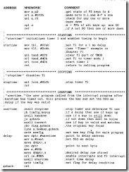
The important feature of the program is that the main program will check a T1ag to see whether there is any keyboard activity. If the Hag is set, then the program finds the key stored in a RAM location and resets the Hag. The getting of the key is "transparent" to the main program; it is done in the interrupt program. The keyboard is still polled by the main program, but the interrupt program gets the key after that. The program named "Hard time" from Chapter 7 is used for the time delay. The keyboard user may notice some sluggishness in response if the main program takes so long to look that the keyboard initiation sequence is not done every quarter-second or so.
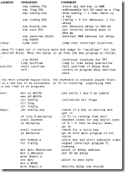
Inkey
The program "lnkey" uses hardware timer T1 to generate all time delays. The keyboard sequence is initiated when a key is found to be down; otherwise, the program continues and checks for a key down in the next look. A key down initiates a de bounce time delay in timer T1 and sets a timer Hag to notify the interrupt program of the use of the timer. The interrupt program checks that a key is still down and is valid. Valid keys are stored, and a Hag is set that may be tested by the main program. The interrupt program then begins the key-up delay and sets the timer Hag to signify this condition. After each key-up delay, the interrupt program checks for all keys up. The time delay is reinitialized until all keys are up and the timer interrupts are halted.
COMMENT
This program is large enough to require additional attempts to make it legible. All of the subroutines are arranged in alphabetical order.
Codekey
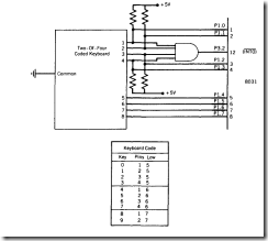
The completely interrupt-driven small keyboard example given in this section requires no program action until a key has been pressed. Hardware must be added to attain a completely interrupt-driven event. The circuit of Figure 8.4 is used.
FIGURE 8.4 Keyboard Configuration Used for "Codekey” Program
The keyboard is a two-of-eight type which codes the ten keys as follows:
|
KEY |
CODE(HEX) |
|
0 |
EE |
|
1 |
ED |
|
2 |
EB |
|
3 |
E7 |
|
4 |
DE |
|
5 |
DD |
|
6 |
DB |
|
7 |
D7 |
|
8 |
BE |
|
9 |
BD |
An inspection of the code reveals that each nibble has only one bit that is low for each key and that two of the eight bits are uniquely low for each key. If more than one key is pressed, then three or more bits go low, signaling an invalid condition. This popular scheme allows for up to 16 keys to be coded in this manner. Unlike the lead-per-key arrangement, only four of the lines must be active-low ORed to generate an interrupt.
The hardware serves to detect when any number of keys are hit by using an AND gate to detect when any nibble bit goes low. The high-to-low transition then serves to interrupt the microcontroller on port 3.2 (I͞N͞T͞0 ). The interrupt program reads the keys connected to port I and uses timer TO to generate the de bounce time and T1 for the keys-up delay. The total delay possible at 16 megahertz for the timers is 49.15 milliseconds, which covers the delay times used in the previous examples.
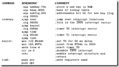
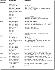
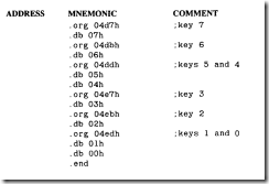
The program "Codekey" which is interrupt driven by a high-to-low transition on I͞N͞T͞0 . Timers TO and T1 generate the de bounce and delay times in an interrupt mode. The I͞N͞T͞0 interrupt input is disabled until all keys have been seen up for the T1 delay. A lookup table is used to verify that only one key is pressed.
COMMENT
The lookup table will work only if every bit from 0400h to 04FFh that is not a .db assignment is FFh. Most EProM S will be FFh when erased, and the assembler will not program unspecified locations. The table will have to be assembled so that an FFh is at every non-key location if this is not true.
Key bounce down is eliminated by the TO delay, and key bounce up, by the T1 delay. More than two keys down is detected by the self-coding nature of the keyboard. A held key does not interrupt the edge-triggered I͞N͞T͞O input.
Program for a Large Matrix Keyboard
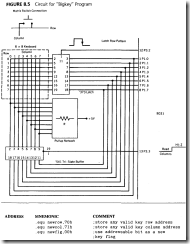
A 64-key keyboard, arranged as an 8-row by 8-column matrix will be interfaced to the 8051 rnicrocontroller, as shown in Figure 8.5. Port I will be used to bring each row low, one row at a time, using an 8-bit latch that is strobed by port 3.2. Pl will then read the 8-bit column pattern by enabling the tri-state buffer from port 3.3. A pressed key will have a unique row-column pattern of one row low, one column low. Multiple key presses are rejected by either an invalid pattern or a failure to match for three complete cycles. Each row is scanned at an interval of I millisecond, or an 8 millisecond cycle for the entire keyboard. A valid key must be seen to be the same key for 3 cycles (24 milliseconds). There must then be three cycles with no key down before a new key will be accepted. The I millisecond delay between scans is generated by timer TO in an interrupt mode.
Bigkey
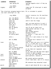
The "Bigkey" program scans an 8 x 8 keyboard matrix using TO to generate a periodic I ms delay in an interrupt mode. Each row is scanned via an external latch driven by port I and strobed by port 3.2. Columns are read via a tri-state buffer under control of port 3.3. Keys found to be valid are passed to the main program by setting the flag "new fig" and placing the key identifiers in locations "newrow" and "newcol." The main program resets "newflg" when the new key is fetched. R4 is used as a cycle counter for successful matches and up time cycles. R5 is used to hold the row scan pattern: only one bit low.
COMMENT
Once begun by the main program, TO continues to time out and generate the row scan pattern in the interrupt program. To the main program, the keys appear in some unknown way; the interrupt program is sA/D to run in the "background."
There is considerable adjustment (tweak) in this program to accommodate keys with various bounce characteristics. The de bounce time can be altered in a gross sense by changing the number of cycles (R4) for acceptance and in a fine way by changing the basic row scan time (TO).
This same program can be used to monitor any multipoint array of binary data points. The array can be expanded easily to a 16 x 16 matrix by adding one more latch and tristate buffer and using two more port 3 pins to generate the latch and enable strobes.
Note that only A can compare against memory contents in a CINE instruction.
Displays
If keyboards are the predominant means of interface to human input, then visible displays are the universal means of human output. Displays may be grouped I͞N͞T͞0 three broad categories:
1. Single light(s)
2. Single character(s)
3. Intelligent alphanumeric
Single light displays include incandescent and, more likely, LED indicators that are treated as single binary points to be switched off or on by the program. Single character displays include numeric and alphanumeric arrays. These may be as simple as a sevensegment numeric display up to intelligent dot matrix displays that accept an 8-bit ASCII character and convert the ASCII code to the corresponding alphanumeric pattern. Intelligent alphanumeric displays are equipped with a built-in microcontroller that has been optimized for the application. Inexpensive displays are represented by multicharacter LCD windows, which are becoming increasingly popular in hand-held wands, factory fl00r terminals, and automotive dashboards. The high-cost end is represented by CRT ASCII terminals of the type commonly used to interface to a multi-user computer.
The individual light and intelligent single-character displays are easy to use. A port presents a bit or a character then strobes the device. The intelligent ASCII terminals are normally serial devices, which are the subject of Chapter 9.
The two examples in this section-seven-segment anp intelligent LCD displaysrequire programs of some length.
Seven-Segment Numeric Display
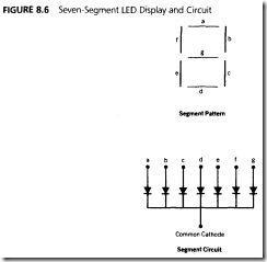
Seven-segment displays commonly contain LED segments arranged as an "8," with one common lead (anode or cathode) and seven individual leads for each segment. Figure 8.6 shows the pattern and an equivalent circuit representation of our example, a common cathode display. If more than one display is to be used, then they can be time multiplexed; the human eye can not detect the blinking if each display is relit every JO milliseconds or so. The I 0 milliseconds is divided by the number of displays used to find the interval between updating each display.
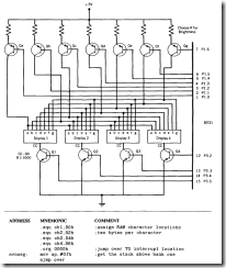
The example examined here uses four seven-segment displays; the segment information is output on port I and the cathode selection is done on ports 3.2 to 3.5, as shown in
Figure 8.7. A segment will he lit only if the segment line is brought high and the common cathode is brought low.
Transistors must be used to handle the currents required by the LEDs, typically io milliamperes for each segment and 70 milliamperes for each cathode. These are average current values; the peak currents will be four times as high for the 2.5 milliseconds each display is illuminated.
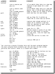
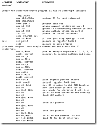
The program is interrupt driven by TO in a manner similar to that used in the program "Bigkey." The interrupt program goes to one of four two-byte character locations and finds the cathode segment pattern to be latched to port I and the anode pattern to be latched to port 3. The main program uses a lookup table to convert from a hex number to the segment pattern for that number. In this way, the interrupt program automatically displays whatever number the main program has placed in the character locations. The main program loads the character locations and is not concerned with how they are displayed.
Svnseg
The program "svnseg" displays characters found in locations "chi" to "ch4" on four common-cathode seven-segment displays. Port I holds the segment pattern from the low byte of chx; port 3 holds the cathode pattern from the high byte of chx. T0 generates a 2.5 ms delay interval between characters in an interrupt mode. The main program uses a lookup table to convert from hex to a corresponding pattern. ro of bank one is dedicated as a pointer to the displayed character.
FIGURE 8.7 Seven-Segment Display Circuit Used for "Svnseq" Program
|
COMMENT |
Using bank 1 as a dedicated bank for the interrupt routine cuts down on the need for pushes and pops. Bank 1 may be selected quickly, giving access to the eight registers while saving the bank 0 registers. Note that the stack, at reset, points to ro of bank 1, so that it must be relocated.
The intensity of the display may also be varied by blanking the displays completely for some interval using the program.
Intelligent LCD Display
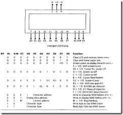
In this section, we examine an intelligent LCD display of two lines, 20 characters per line, that is interfaced to the 8051 . The protocol (handshaking) for the display is shown in Figure 8.8, and the interface to the 8051 in Figure 8.9.
The display contains two internal byte-wide registers, one for commands (RS = 0) and the second for characters to be displayed (RS = l). It also contains a user-programmed RAM area (the character RAM) that can be programmed to generate any desired character that can be formed using a dot matrix. To distinguish between these two data areas, the hex command byte 80 will be used to signify that the display RAM address 00h is chosen.
FIGURE 8.8 Intelligent LCD Display
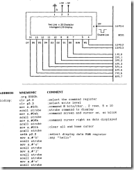
Port 1 is used to furnish the command or data byte, and ports 3.2 to 3.4 furnish regis ter select and read/write levels.
The display takes varying amounts of time to accomplish the functions listed in fissure 8.8. LCD bit 7 is monitored for a logic high (busy) to ensure the display is not’"’"’ written. A slighT1y more complicated LCD display (4 lines x 40 characters) is curn-nr}, being used in medical diagnostic systems to run a very similar program.
Lcdisp
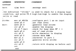
The program "Icdisp" sends the message "hello" to an intelligent LCD display shown rn Figure 8.8. Port 1 supplies the data byte. Port 3.2 selects the command (0) or data t I 1 registers. Port 3.3 enables a read (0) or write (I) level, and port 3.4 generates an active. low-enable strobe.
FIGURE 8.9 Intelligent LCD Circuit for "Lcdisp" Program
COMMENT
lf long character strings are to be displayed, then a subroutine could be written that receives the beginning address of the string. The subroutine then displays the characters until a unique "end-of-string" character is found.
