DATA COPY (LOAD) OPERATIONS
In this section, we focus on three types of data copy operations: data copy related to microprocessor registers, memory, and I/Os. Instructions frequently used are illustrated below, and the Z80 block transfer instruction will be discussed later in the chapter. In addition, one machine control instructionــــHALTــــis introduced; this instruction is necessary to indicate the end of a program.
Data Copy (Load) Among Registers
In this group, we have three types of instructions: data copy from one register to another, loading 8-bit data into a register, and loading 16-bit data into a register pair.
|
Opcode |
Operand |
Bytes
|
Addressing Modes |
Description |
|
LD |
Rd , rs † Example: |
1 LD B,C |
Register |
Copy data from source register rs to destination register rd. In this mode, operand is a part of the Opcode. |
|
LD |
r†, 8-bit Example: |
2 LD B,32H |
Immediate |
Load 8-bit data of the second byte into the specified register. In this mode, the second byte is the operand. |
|
LD |
rp, 16-bit Example: |
3 LD HL,1850H |
Immediate Extended |
Load 16 bits into the specified register pair. In this mode, two bytes following the opcode are the operands. |
|
LD |
rx , 16- bit Example: |
4 LD IX,2050H |
Immediate Extended |
Load 16 bits into the specified index register. |
|
HALT |
|
1 |
|
This is a machine control instruction. The processor stops executing and enters into Wait state. |
General Characteristics
1. Copy (Load) instructions do not affect flags.
2. The operands of copy instructions specify a destination register first, followed by a source register; they are separated by a comma.
3. The data byte is copied without modifying the contents of a source register.
4. A 16-bit operand is stored in two consecutive memory locations in the reversed order: the low-order byte first, followed by the high-order byte.
5. The instructions related to the index registers IX and IY have two-byte Opcodes.
6. Data cannot be loaded directly into the flag register, program counter (PC), and alternate registers: the immediate addressing mode is not available for these registers.
Description
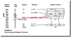
1. The first instruction LD A, 97H is a 2-byte instruction; the opcode 3EH and the operand 97H are stored in the first two memory locations. This instruction loads: 97H into the accumulator .
2. The second instruction is a 3-byte instruction that loads 16-bit data (2050H) into the HL registers. The low-order byte (50H) is stored first in memory location 2003H, followed by the high-order byte (20H).
3. The third instruction (IX, 2075H) is a 4-byte instruction; it has a 2- byte opcode (DD and 21). This instruction loads 16-bit data (2075H) into the index register IX.
4. The remaining two instructions are 1-byte instructions; they copy data from one register to another as shown .It is important to note that the copy operations do not destroy the contents of the source registers. Figure 8.1 shows that registers A and H retain their contents after the copy operations.
5. The last instruction (HALT) is a machine control instruction; it forces the machine into the Wait state
