Actuator disc approach
Introduction
In the following sections, the aerodynamic theory of the HAWT is gradually developed, starting with the simple 1D momentum analysis of the actuator disc and followed by the more detailed analysis of the blade element theory. The flow state just upstream of the rotor plane forms the so-called inflow condition for the rotor blades and from which the aerodynamic forces acting on the blades can be determined. The highly regarded BEM method is outlined and used extensively. A number of worked examples are included at each stage of development to illustrate the application of the theory. Detailed calculations using the BEM method were made to show the influence of various factors, such as the tip-speed ratio and blade number on performance. Further development of the theory includes the application of Prandtl’s tip loss correction factor, which corrects for a finite number of blades. Glauert’s optimization analysis is developed and used to determine the ideal blade shape for a given lift coefficient and to show how the optimum rotor power coefficient is influenced by the choice of tip-speed ratio.
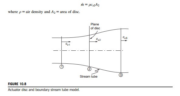
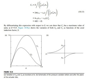
The concept of the actuator disc was used in Chapter 6 as a method of determining the 3D flows in compressor and turbine blade rows. Betz (1926) in his seminal work on the flow through wind- mill blades used a much simpler version of the actuator disc. As a start to understanding the power production process of the turbine consider the flow model shown in Figure 10.8 where the rotor of the HAWT is replaced by an actuator disc. It is necessary to make a number of simplifying assumptions concerning the flow but, fortunately, the analysis yields useful approximate results.
Theory of the actuator disc
The following assumptions are made:
i. steady uniform flow upstream of the disc;
ii. uniform and steady velocity at the disc;
iii. no flow rotation produced by the disc;
iv. the flow passing through the disc is contained both upstream and downstream by the boundary stream tube;
v. the flow is incompressible.
Because the actuator disc offers a resistance to the flow, the velocity of the air is reduced as it approaches the disc and there will be a corresponding increase in pressure. The flow crossing through the disc experiences a sudden drop in pressure below the ambient pressure. This discontinuity in pressure at the disc characterizes the actuator. Downstream of the disc there is a gradual recovery of the pressure to the ambient value.
We define the axial velocities of the flow far upstream (x- 2N), at the disc (x 5 0) and far downstream (x-N) as cx1, cx2 and cx3, respectively. From the continuity equation, the mass flow is
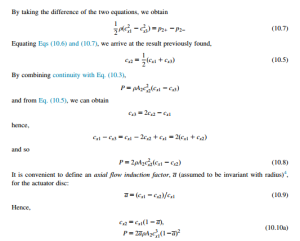
This is the proof developed by Betz (1926) to show that the velocity of the flow in the plane of the actuator disc is the mean of the velocities far upstream and far downstream of the disc. We should emphasize again that wake mixing, which must physically occur far downstream of the disc, has so far been ignored.
An alternative proof of Betz’s result
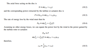
The air passing across the disc undergoes an overall change in velocity (cx1 2 cx3) and a corresponding rate of change of momentum equal to the mass flow rate multiplied by this velocity change. The force causing this momentum change is equal to the difference in pressure across the disc times the area of the disc. Thus,
The pressure difference Δp is obtained by separate applications of Bernoulli’s equation to the two flow regimes of the stream tube.
Referring to regions 1-2 in Figure 10.8,
The power coefficient
For the unperturbed wind (i.e., velocity is cx1) with the same flow area as the disc (A2 5 πR2), the kinetic power available in the wind is
The axial force coefficient
The axial force coefficient is defined as
EXAMPLE 10.2
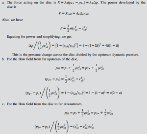
Using the theoretical flow model of a wind turbine proposed by Betz obtain expressions for the static pressure changes:
a. across the actuator disc;
b. up to the disc from far upstream;
c. from the disc to far downstream.
The pressure immediately before the disc is p21. The pressure immediately after the disc is p22.
Solution
a. The force acting on the disc is X 5 A2ðp21 2 p22Þ 5 A2Δp. The power developed by the disc is
Correcting for high values of a
It is of some interest to examine the theoretical implications of what happens at high values of a and compare this with what is found experimentally. From the actuator disc analysis, we found that the velocity in the wake far downstream was determined by cx3 5 cx1ð1 2 2aÞ; and this becomes zero when a 5 0:5. In other words, the actuator disc model has already failed as there can be no flow when a 5 0:5. It is as if a large flat plate had been put into the flow, completely replacing the rotor. Some opinion has it that the theoretical model does not hold true for values of a even as low as 0.4. So, it becomes necessary to resort to empirical methods to include physical reality.
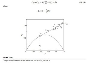
Figure 10.10 shows experimental values of CX for heavily loaded turbines plotted against a, taken from various sources, together with the theoretical curve of CX versus a given by Eq. (10.13). The part of this curve in the range 0:5 , a , 1:0, shown by a broken line, is invalid as already explained. The experiments revealed that the vortex structure of the flow downstream disintegrates and that wake mixing with the surrounding air takes place. Various authors including Glauert (1935), Wilson (1976), and Anderson (1980), have presented curves to fit the data points in the regime a . 0:5. Anderson obtained a simple “best fit” of the data with a straight line drawn from a point denoted by CXA located at a 5 1 to a tangent point T, the transition point, on the theoretical curve located at a 5 aT. It is easy to show, by differentiation of the curve CX 5 4að1 2 aÞ then fitting a straight line, with the equation,
Anderson recommended a value of 1.816 for CXA. Using this value, Eq. (10.14) reduces to
Estimating the power output
Preliminary estimates of rotor diameter can easily be made using simple actuator disc theory. A number of factors need to be taken into account, i.e., the wind regime in which the turbine is to operate and the tip-speed ratio. Various losses must be allowed for the main ones being the mechanical transmission including gearbox losses and the electrical generation losses. From the actuator disc theory, the turbine aerodynamic power output is
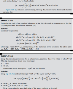
Under theoretical ideal conditions, the maximum value of Cp 5 0.593. According to Eggleston and Stoddard (1987), rotor Cp values as high as 0.45 have been reported. Such high, real values of Cp relate to very precise, smooth aerofoil blades and tip-speed ratios above 10. For most machines of good design a value of Cp from 0.3 to 0.35 would be possible. With a drive train efficiency, ηd, and an electrical generation efficiency, ηg, the output electrical power would be
EXAMPLE 10.5
Determine the size of rotor required to generate 20 kW of electrical power in a steady wind of 7.5 m/s. It can be assumed that the air density, ρ 5 1.2 kg/m3, Cp 5 0.35, ηg 5 0.75, and ηd 5 0.85.
Solution
From this expression, the disc area is
Hence, the diameter is 21.2 m.
