Blade element theory
Introduction
It has long been recognized that the work of Glauert (1935) in developing the fundamental theory of aerofoils and airscrews is among the great classics of aerodynamic theory. Glauert also generalized the theory to make it applicable to wind turbines and, with various modifications, it is still used in turbine design. It is often referred to as the momentum vortex blade element theory or more simply as the blade element method. However, the original work neglected an important aspect: the flow periodicity resulting from the turbine having a finite number of blades. Glauert assumed that elementary radial blade sections could be analyzed independently, which is valid only for a rotor with an infinite number of blades. However, several approximate solutions are available (those of Prandtl and Tietjens (1957) and Goldstein (1929)), which enable compensating corrections to be made for a finite number of blades. The simplest and most often used of these, called the Prandtl correction factor, will be considered later in this chapter. Another correction that is considered is empirical and applies only to heavily loaded turbines when the magnitude of the axial flow induction factor a exceeds the acceptable limit of the momentum theory. According to Sharpe (1990), the flow field of heavily loaded turbines is not well understood, and the results of the empirical analysis mentioned are only approximate but better than those predicted by the momentum theory.
The vortex system of an aerofoil
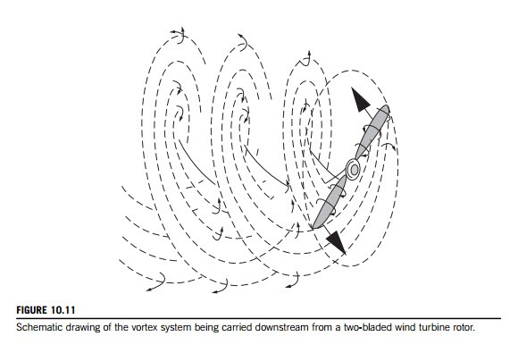
To derive a better understanding of the aerodynamics of the HAWT than was obtained earlier from simple actuator disc theory, it is now necessary to consider the forces acting on the blades. We may regard each radial element of a blade as an aerofoil. The turbine is assumed to have a constant angular speed Ω and is situated in a uniform wind of velocity cx1 parallel to the axis of rotation. The lift force acting on each element must have an associated circulation (see Section 3.4) around the blade. In effect there is a line vortex (or a set of line vortices) along the aerofoil span. The line vortices that move with the aerofoil are called bound vortices of the aerofoil. As the circulation along the blade length can vary, trailing vortices will spring from the blade and will be convected downstream with the flow in approximately helical paths, as indicated for a two-bladed wind turbine in Figure 10.11. It will be observed that the helices, as drawn, gradually expand in radius as they move downstream (at the wake velocity) and the pitch between each sheet becomes smaller because of the deceleration of the flow.
Wake rotation
In the previous analysis of the actuator disc, it was assumed that no rotation was imparted to the flow. It is evident that the torque exerted on the rotor disc by the air passing through it requires an equal and opposite torque to be exerted on the air. As a consequence, this reaction torque causes the air leaving the rotor to rotate incrementally in the opposite direction to that of the rotor. Thus, the wakes leaving the rotor blades will have a velocity component in the direction tangential to the blade rotation as well as an axial velocity component.
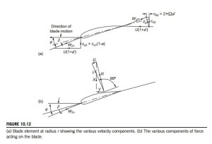
The flow entering the rotor has no rotational motion at all. The flow exiting the rotor has rotation and this remains constant as the flow travels downstream. We can define the change in the tangential velocity in terms of a tangential flow induction factor, a0. Downstream of the disc in the induced tangential velocity cθ2 defined as 2Ωra0 is as shown in Figure 10.12(a). The complete transfer of rotational energy is assumed to take place across the rotor disc. This is actually impossible as the disc is defined as having no thickness. The rotational velocity component cθ2 develops physically as the actual flow progresses toward the trailing edge plane.
Glauert regarded the exact evaluation of the interference flow to be of great complexity because of the periodicity of the flow caused by the blades. He asserted that for most purposes it is sufficiently accurate to use circumferentially averaged values, equivalent to assuming that the thrust and the torque carried by the finite number of blades are replaced by uniform distributions of thrust and torque spread over the whole circumference at the same radius.
Consider such an elementary annulus of a HAWT of radius r from the axis of rotation and of radial thickness dr. Let dτ be the element of torque equal to the rate of decrease in angular momentum of the wind passing through the annulus. Thus,
In the actuator disc analysis, the value of a (denoted by a) is a constant over the whole of the disc. With blade element theory, the value of a is a function of the radius. This is a fact that must not be overlooked. A constant value of a could be obtained for a wind turbine design with blade element theory, but only by varying the chord and the pitch in some special way along the radius. This is not a useful design requirement.
Assuming the axial and tangential induction factors a and a0 are functions of r, we obtain an expression for the power developed by the blades by multiplying the above expression by Ω and integrating from the hub rh to the tip radius R:
Forces acting on a blade element
Consider now a turbine with Z blades of tip radius R each of chord l at radius r and rotating at angular speed Ω. The pitch angle of the blade at radius r is β measured from the zero lift line to the plane of rotation. The axial velocity of the wind at the blades is the same as the value deter- mined from actuator disc theory, i.e., cx2 5 cx1(1 2 a), and is perpendicular to the plane of rotation.
Figure 10.12(a) shows the blade element moving from right to left together with the velocity vectors relative to the blade chord line at radius r. The resultant of the relative velocity immediately upstream of the blades is
and this is shown as impinging onto the blade element at angle φ to the plane of rotation. It will be noticed that the relative velocity at blade exit is reduced to w22 as a result of the wake mentioned earlier. The following relations will be found useful in later algebraic manipulations:
Figure 10.12(b) shows the lift force L and the drag force D drawn (by convention) perpendicular and parallel to the relative velocity at entry, respectively. In the normal range of operation, D although rather small (1-2%) compared with L, is not to be entirely ignored. The resultant force, R, is seen as having a component in the direction of blade motion. This is the force contributing to the positive power output of the turbine.
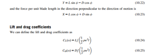
From Figure 10.12 (b), the force per unit blade length in the direction of motion is
where, by the convention employed for an isolated aerofoil, w is the incoming relative velocity and l is the blade chord. The coefficients CL and CD are functions of the angle of incidence, α 5 φ 2 β, as defined in Figure 10.12 as well as the blade profile and blade Reynolds number. In this chapter, the angle of incidence is understood to be measured from the zero lift line (see Section 5.15) for which the CL versus α curve goes through zero. It is important to note that Glauert (1935), when considering aerofoils of small camber and thickness, obtained a theoretical expression for the lift coefficient,
The theoretical slope of the curve of lift coefficient against incidence is 2π per radian (for small values of α) or 0.11 per degree but, from experimental results, a good average generally accepted is 0.1 per degree within the prestall regime. This very useful result will be used extensively in calculating results later. However, measured values of the lift-curve slope reported by Abbott and von Doenhoff (1959) for a number of NACA four- and five-digit series and NACA 6-series wing
sections, measured at a Reynolds number of 6 3 106, gave 0.11 per degree. But these blade profiles were intended for aircraft wings, so some departure from the rule might be expected when the application is the wind turbine.
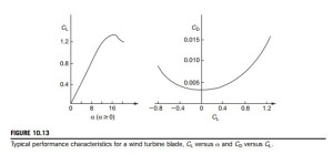
Again, within the prestall regime, values of CD are small and the ratio of CD/CL is usually about 0.01. Figure 10.13 shows typical variations of lift coefficient CL plotted against incidence α and drag coefficient CD plotted against CL for a wind turbine blade tested beyond the stall state. The blades of a wind turbine may occasionally have to operate in poststall conditions when CD becomes large; then the drag term needs to be included in performance calculations. Details of stall modeling and formulae for CD and CL under poststall conditions are given by Eggleston and Stoddard (1987).
The correct choice of aerofoil sections is very important for achieving good performance. The design details and the resulting performance are clearly competitive and not much information is actually available in the public domain. The US Department of Energy (DOE) developed a series of aerofoils specifically for wind turbine blades. These aerofoils were designed to provide the necessarily different performance characteristics from the blade root to the tip while accommodating the structural requirements. Substantially increased energy output (from 10% to 35%) from wind turbines with these new blades have been reported. The data are cataloged and is available to the US wind industry.5 Many other countries have national associations, research organizations, and conferences relating to wind energy and contact details are listed by Ackermann and So¨ der (2002).
Connecting actuator disc theory and blade element theory
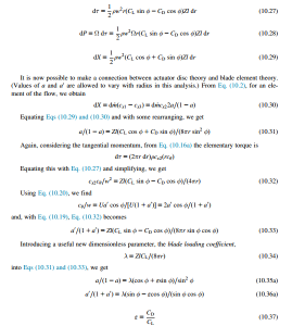
The elementary axial force and elementary force exerted on one blade of length dr at radius r are
For a turbine having Z blades and using the definitions for CL and CD given by Eqs (10.24) and (10.25), we can write expressions for the elementary torque, power, and thrust as
Tip-speed ratio
A most important nondimensional parameter for the rotors of HAWTs is the tip-speed ratio, defined as
This parameter controls the operating conditions of a turbine and strongly influences the values of the flow induction factors, a and a0.
Using Eq. (10.38) in Eq. (10.21), we write the tangent of the relative flow angle φ as
Turbine solidity
A primary nondimensional parameter that characterizes the geometry of a wind turbine is the blade solidity, σ. The solidity is defined as the ratio of the blade area to the disc area:
Solving the equations
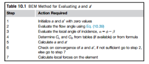
The foregoing analysis provides a set of relations which can be solved by a process of iteration, enabling a and a0 to be determined for any specified pitch angle β, provided that convergence is possible. To obtain faster solutions, we will use the approximation that εD0 in the normal efficient range of operation (i.e., the prestall range). Equations (10.35a) and (10.36a) can now be written as
These equations are about as simple as it is possible to make them and they will be used to model some numerical solutions.
