Inductive Action of the Wind
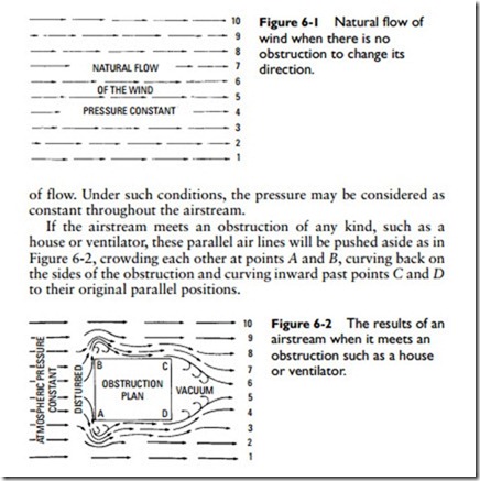
When the wind blows without encountering any obstruction to change its direction, its movement may be represented by a series of parallel arrows, as in Figure 6-1. The arrows indicate the direction
A vacuum is formed here as indicated by the suction lines (that is, the arrows that curve back and inward toward the space occupied by the vacuum). This vacuum (or reduction in pressure) is what causes inductive action.
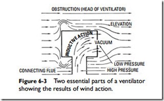
A ventilator can be constructed in such a way as to make this inductive action effective for ventilation. Figure 6-3 shows the two essential parts of a simple ventilator: the head and connecting flue. The head is open at one end and closed at the other and in actual construction is pivoted to rotate, guided by a vane so that the closed end always faces the wind.
As shown in Figure 6-3, the closed end forms an obstruction, which changes the direction of the wind expanding at the closed end and converging at the open end, producing a vacuum inside the
head, which induces an upward flow of the air through the flue and out through the head. This is inductive action of the wind.
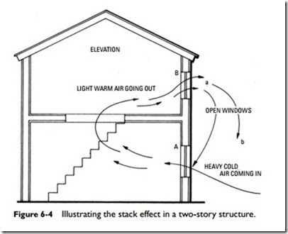
The stack or flue effect (see Figure 6-4) produced within a building when the outdoor temperature is lower than the indoor temperature is due to the difference in weight of the warm column of air within the building and the cooler air outside. The flow due to the stack (flue) effect is proportional to the square root of the draft
head. The formula for determining the rate of flow is as follows:
Q = 9.4A 2h (t – t0)
where Q = airflow, cubic feet per minute.
A = free area of inlets or outlets (assumed equal), square feet.
h = height from inlets to outlets, feet.
t = average temperature of indoor air at height h, °F.
t0 = temperature of outdoor air, °F.
9.4 = constant of proportionality, including a value of percent for effectiveness of openings. This should be reduced to 50 percent (constant = 7.2) if conditions are not favorable.
Induced Draft
A closed flue (stack) or chimney will induce a draft or draw air. In other words, it will cause the air to rise from the bottom level (or room level) to the top. Consider the schematic of a stack shown in Figure 6-5. The air is cool at the bottom of the stack and hot at the top. Each unit of air in traversing the stack expands as the temperature increases and becomes lighter. Assuming that cube A in Figure 6-5 represents 1 lb of air and that the initial volume undergoes first eight expansions and then sixteen, the corresponding weight of the initial volume (1 lb) decreases to 1⁄8 lb and then to 1⁄16 lb. Accordingly the sum of the weights of unit volume in ascending is 1 + 1⁄8 + 1⁄16 or 13⁄16 lbs. On the outside of the stack the volume and weight of each unit of air remain the same so that considering three units a, b, c of decreasing weights in the stack, there are three units of a‘, b‘, c‘ of constant weight outside the stack, the total weight outside the stack being 3 lbs and only 13⁄16 lbs inside the stack. As a result of the downward force (3 lbs) outside the stack being greater than that in the stack, the heavy units a‘, b‘, c‘ push the lighter units a, b, c up and out of the stack, thus inducing a draft as indicated by the lever scales in Figure 6-5. For purposes of explanation, induced draft may be considered virtually the same as thermal effect.


