Exhaust-Hood Design Recommendations
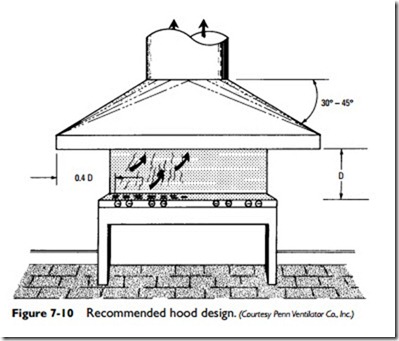
A properly designed exhaust hood (see Figure 7-10) is an important part of a local ventilation system. The following recommendations are offered as design guidelines:
1. Use the shortest duct run possible.
2. Avoid the use of elbows and transitions.
3. Size the exhaust hood to provide a minimum 100 fpm face velocity (150 fpm for island-type work).
4. Provide sufficient hood overhang on all sides to overlap work area.
5. Use more than one exhaust fan on very large hoods.
6. Use as many individual hood and duct systems as possible (that is, try to avoid grouping hoods together on the same duct system).
7. Use filters where required. Velocities over filters should be sized in accordance with filter manufacturer’s recommendations.
8. Provide makeup air units.
Fan Motors
Most fans used in heating, ventilating, and air-conditioning installations are powered by electric motors. Because of the small size of many of these fans, the majority are equipped with direct-connected motors. A V-belt drive arrangement is used with larger fans, particularly centrifugal fans used in forced warm-air furnaces or the larger ventilating units found in commercial and industrial installations.
It is the general rule to select a fan one size larger than the fan requirements for the installation. This is particularly so in installations that may require the movement of large volumes of air for short intervals.
The advantage of fans equipped with a belt-drive arrangement is that adjustments can be made for different speeds. It is simply a matter of changing the pulley size. A belt drive is especially desir- able when the required horsepower requirement is in doubt.
A fan wheel directly connected to the motor shaft is the best arrangement, but this is only feasible with the smaller centrifugal fans and propeller fans under 60 inches in diameter.
A direct-connected fan is generally driven by a single-phase AC motor of the split-phase, capacitor, or shaded-pole type. The capacitor motor is recommended when there are current limitations. Its major advantage is its greater efficiency electrically. The major dis- advantage of such motors is that they are usually designed to operate at only one speed. A damper arrangement can be used to throttle the air when it becomes necessary to vary the air volume or pressure of the fan.
The variation of pressure and air volume in larger fan installations (for example, mechanical draft fans) can be accomplished by means of a constant-speed, direct-connected motor equipped with movable guide vanes in the fan inlet.
The National Electrical Manufacturer’s Association (NEMA) has recently revised motor voltage designations to conform to sys- tem voltages now present throughout the country. Single-phase motor voltages should now be specified as 115 volts or 230 volts instead of the 110-volt or 220-volt designations formerly in effect. Polyphase voltages should be expressed as 208 volts or 230/460 volts instead of the 220/440 voltages formerly in effect. Motors for special voltages such as 177, 480, or 575 volts are available from many fan manufacturers on special order. Fan motors have been designed to operate satisfactorily over the range of plus or minus 10 percent of the nameplate voltage ratings. Always check the fan motor nameplate voltage ratings before installing the motor.
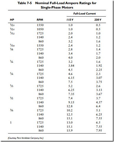
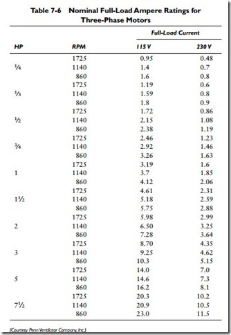
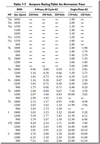
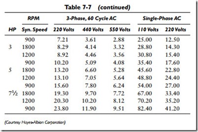
Tables 7-5 and 7-6 list nominal full-load ampere ratings for sin- glephase and three-phase motor voltages. The amperes given are approximate values only and represent averages compiled from tables of leading motor manufacturers. Compare these with the specific amperages listed for Airmaster fans in Table 7-7.
Overload relay heaters should not be selected solely on the basis of the data listed in Tables 7-5 and 7-6. Heaters must be selected in accordance with the actual motor current as shown on the nameplate. It is also important that ambient temperatures of the area in which the motor control is located be taken into consideration when making heater selections. Ambient compensated overload relays are available for abnormal temperature conditions.
Typical connection diagrams for two-speed, three-phase motors are illustrated in Figures 7-11 and 7-12. Two-speed motors are available for most fan lines. Because all two-speed motors are always single-voltage, it is necessary to specify the available line voltage phase and frequency when ordering.
Examples of fans equipped with the belt-drive arrangement and direct-connected motors are shown in Figures 7-13 and 7-14.
