The Unijunction Transistor
The unijunction transistor is a special transis- tor that has two bases and one emitter. The unijunction transistor (UJT) is a digital device because it has only two states, on or off, and is generally classified with a group of devices known as thyristors. Thyristors are turned completely on or completely off. Thyristors include devices such as the silicon- controlled rectifier (SCR), triac, diac, and the unijunction transistor.
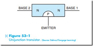
The unijunction transistor is made by combining three layers of semi-conductor material as shown in Figure 53–1. The schematic symbol with polarity connections and the base diagram is shown in Figure 53–2.
UJT CHARACTERISTICS
The UJT has two paths for current flow. One path is from B2 to B1. The other path is through the emitter and base #1. In its normal state, there is no current flow through either path until the voltage applied to the emitter reaches about 10 volts higher than the voltage applied to base #1. When the voltage applied to the emitter reaches about 10 volts more positive than the voltage applied to base #1, the UJT turns on and current flows through the B1–B2 path and from the emitter through base #1. Current will continue to flow through the UJT until the voltage applied to the emitter drops to a point that it is only about 3 volts higher than the voltage applied to B1. When the emitter voltage drops to this point, the UJT will turn off and remain turned off until the voltage applied to the emitter again becomes about 10 volts higher than the voltage applied to B1.
CIRCUIT OPERATION
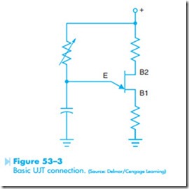
The unijunction transistor is generally connected into a circuit similar to the circuit shown in Figure 53–3. The variable resistor controls the rate of charge time of the capacitor. When the capaci- tor has been charged to about 10 volts, the UJT turns on and discharges the capacitor through the emitter and base #1. When the capacitor has been discharged to about 3 volts, the UJT turns off and permits the capacitor to begin charging again. By varying the resistance connected in series with the capacitor, the amount of time needed for charging the capacitor can be changed, thereby controlling the pulse rate of the UJT (T = RC).
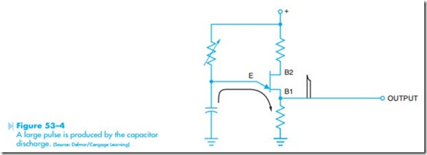
The UJT can furnish a large output pulse, because the output pulse is produced by the discharging capacitor, Figure 53–4. This large output pulse is generally used for triggering the gate of an SCR.
The pulse rate is determined by the amount of resistance and capacitance connected to the emitter of the UJT. However, the amount of capacitance that can be connected to the UJT is limited. For instance, most UJTs should not have a capacitor larger than 10 μf connected to them. If the capacitor is too large, the UJT will not be able to handle the current spike produced by the capacitor, and the UJT could be damaged.
TESTING THE UJT
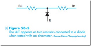
The unijunction transistor can be tested with an ohmmeter in a manner very similar to testing a common junction transistor. The UJT will appear to the ohmmeter to be a connection of two resis- tors connected to a common junction diode. The common junction point of the two resistors will appear to be at the emitter of the UJT as shown in Figure 53–5. When the positive lead of the ohm- meter is connected to the emitter, a diode junction should be seen from the emitter to base #2 and another diode connection from the emitter to base #1. If the negative lead of the ohmmeter is connected to the emitter of the UJT, no connection should be seen between the emitter and either base.
The following step-by-step procedure can be used to test a unijunction transistor.
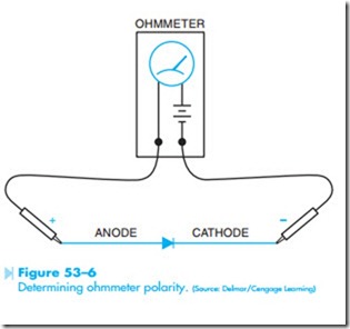
1. Using a junction diode, determine which ohmmeter lead is positive and which is negative. The ohmmeter will indicate continuity when the positive lead is connected to the anode and the negative lead is connected to the cathode, Figure 53–6.
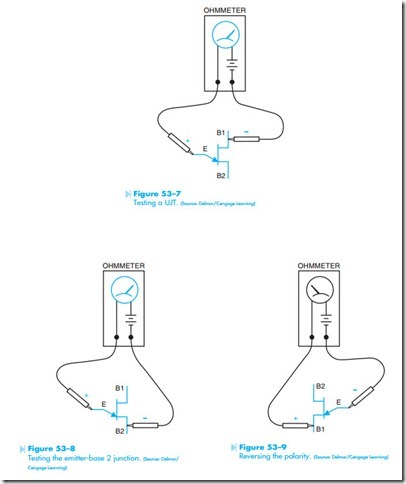
2. Connect the positive ohmmeter lead to the emitter lead and the negative lead to base #1. The ohmmeter should indicate a forward diode junction, Figure 53–7.
3. With the positive ohmmeter lead connected to the emitter, reconnect the negative lead to base #2. The ohmmeter should again indicate a forward diode junction, Figure 53–8.
4. If the negative ohmmeter lead is connected to the emitter, no continuity should be indicated when the positive lead is connected to base #1 or base #2, Figure 53–9.
