ELECTRONIC CONTROL OF BLOWER MOTOR AND COMPRESSOR LOCK-OUT
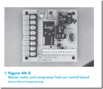
Many units employ electronic control for some of their functions. Troubleshooting for electronic circuit boards is generally accomplished by deter- mining if the board has the proper input information to obtain an output. If the inputs and outputs are correct, the board is good and the problem lies somewhere else in the circuit. The circuit board shown in Figure 44–2 is designed to control the blower for a cooling unit with gas or electric heat.
The circuit board also provides lock-out protection for the compressor.
LOCK-OUT PROTECTION
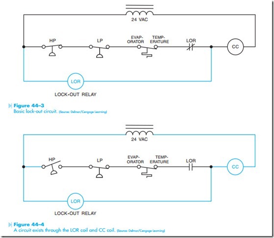
Lock-out protection involves the use of a high- impedance relay that becomes connected in series with the compressor contactor coil in the event of a problem with the compressor circuit. In the circuit shown in Figure 44–3, the coil of the lock-out relay is connected in parallel with the normally closed safety switches used to help protect the compressor. Under normal conditions the high- pressure switch, low-pressure switch, and the low evaporator temperature switch are closed and pro- vide a complete circuit to the compressor contactor coil. Because the lock-out relay coil is connected in parallel with these switches, almost no voltage is dropped across the LOR coil and it remains turned off. If one of the switches should open, however, the lock-out relay coil becomes connected in series with the compressor contactor coil, Figure 44–4. Because the impedance of the lock-out relay coil is much higher than the compressor contactor coil, almost all the 24 volts is dropped across the LOR coil and very little voltage is across the CC coil. The compressor contactor cannot energize because of the low voltage applied to the coil.
The normally closed LOR contact connected in series with the compressor contactor coil opens. If the high-pressure switch should close, the now open LOR contact prevents the compressor contactor from energizing. The circuit will remain in this condition until the control power is turned off and the lock-out relay coil deenergizes. The line volt- age connections for the blower control and lock- out relay circuit board are shown in Figure 44–5. The circuit board and basic controls are shown in Figure 44–6.

