DEFROST TIMER
When the heat pump is used in the heating mode of operation, it removes heat from the air and delivers it inside the living area. This means that the outside heat exchanger is being used as the evaporator and cold refrigerant is circulated through it. Any moisture in the air can cause frost to form on the coil and reduce the airflow through it. This will reduce the efficiency of the unit. For this reason, it is generally necessary to defrost the outside heat exchanger. Defrosting is done by disconnecting the condenser or outside fan motor and reversing the flow of refrigerant through the coil. This causes the unit to temporarily become an air conditioner and warm refrigerant is circulated through the coil.
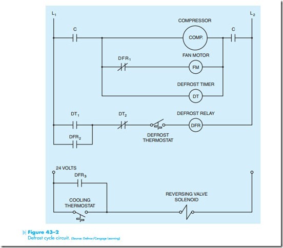
Before the defrost cycle can be activated, two separate control conditions must exist. The defrost thermostat, located on the outside heat exchanger, must be closed; and the defrost timer must permit the defrost cycle to begin. A schematic diagram of a basic defrost control circuit is shown in Figure 43–2. Notice that the defrost timer is connected in parallel with the compressor. This means that the timer can operate only when the compressor is in operation. Notice also that the defrost cycle energizes the reversing valve solenoid. This means that this unit is in the heating mode when the solenoid is deenergized.
Notice the defrost timer contains two contacts, DT1 and DT2. DT1 is normally open and DT2 is normally closed. The defrost relay (DFR) contains three contacts. DFR1 is normally closed and is connected in series with the outside fan motor. DFR2 is normally open and is connected in parallel with contact DT1. Contact DFR3 is normally open and is connected to the reversing valve solenoid.
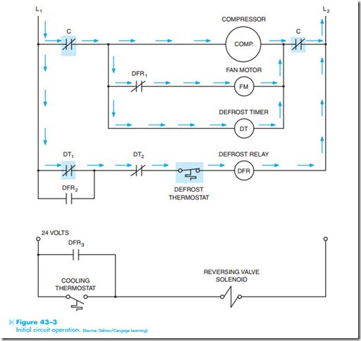
The schematic shown in Figure 43–3 illustrates the condition of the circuit when the defrost cycle first begins. Notice that the defrost timer (DT) has caused contact DT1 to close, but contact DT2 has not opened. The contacts of the defrost timer are operated by two separate cams. The cams are so arranged that contact DT1 will close before DT2 opens.
The schematic in Figure 43–4 illustrates the condition of the circuit immediately after the defrost relay has energized. Notice that all DFR contacts
have changed position. DFR1 contact is now open and the outside fan motor has been disconnected from the circuit. DFR2 contact is closed and is used as a holding contact around contact DT1. DFR3 contact is closed and provides current to the reversing valve solenoid to reverse the flow of refrigerant in the system.
The schematic shown in Figure 43–5 illustrates the condition of the circuit after contact DT1 reopens. Notice that contact DFR2 maintains a cur- rent flow path around the now open DT1 contact and the defrost cycle is permitted to continue. The unit will remain in the defrost cycle until the defrost thermostat is satisfied and opens the circuit, or the defrost timer causes the DT2 contact to open. When this occurs, the system will change back to its original condition shown in Figure 43–2.
Electronic Defrost Timers
Many units now employ an electronic defrost timer similar to the one shown in Figure 43–6. This timer has a fixed 10-minute defrost time. The time interval between defrost cycles can be set by
moving a jumper lead to the proper pin. The time interval can be set for 30, 60, or 90 minutes. Two pins marked TEST can be shorted to reduce the defrost time by a factor of 2, 5, and 6 seconds. This permits the service technician to test the unit without waiting a long period of time. The HOLD terminal permits the timer to accumulate time only during the time that the compressor is in operation. The connection diagram for this module is shown in Figure 43–7.

