Heat Exchangers
Basic Equations
We discuss the principles of simple heat exchange between two flows, which are either running in the same direction (co-flow), or in opposite directions (counter-flow), see Fig. 15.1 for a basic sketch of the set-up. Heat exchange is assumed to be a one-dimensional process, where the temperatures TA (x) and TB (x) of the two flows depend only on the space coordinate in flow direction,
x. In particular, temperature profiles perpendicular to the flow are ignored, that is the given temperatures are cross-sectional averages.
Heat is transferred between the two flows due to different temperatures TA (x) and TB (x). Typically, the inflow temperatures of the flows are given, and one aims at determining the outflow temperatures.
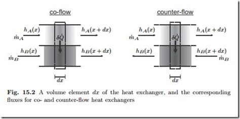
Since the temperatures depend on the location x, we need to balance energy for each location. Figure 15.2 shows small elements of infinitesimal width dx and the corresponding flows and properties for co- and counter-flow settings.
The task at hand is to determine the temperature curves in both flows.
Applying the first law to each flow in each element gives
where in the second equation the upper sign refers to co-flow, and the lower sign refers to counter-flow. The heat exchange between the flows within the element dx is denoted by δQ˙ , and is given by Newton’s law of cooling (4.35), which we write here as
Heat transfer is proportional to the contact area bdx. In the above, the width b is absorbed into the coefficient α and only the length dx of the element is made explicit. The heat transfer coefficient α will be assumed to be constant.
Taylor expansion allows to relate the enthalpy differences to the specific heats and the temperature gradients as
where K1 and K2 are integrating constants, and, as in all equations in this section, the upper sign is for co-flow, and the lower sign is for counter-flow exchangers.


