CURRENT RELATIONSHIPS
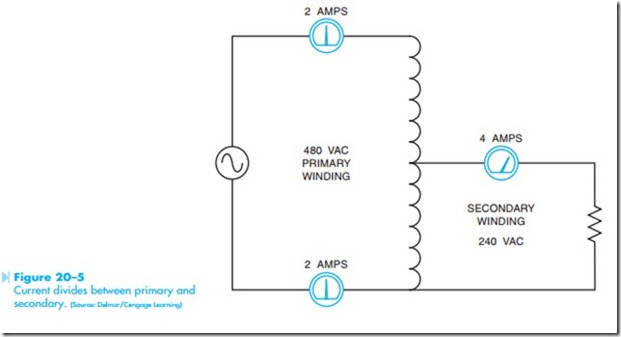
An autotransformer with a 2:1 turns ratio is shown in Figure 20–5. It is assumed that a voltage of 480 volts is connected across the entire winding. Because the transformer has a turns ratio of 2:1, a voltage of 240 volts will be supplied to the load. Ammeters connected in series with each winding indicate the current flow in the circuit. It is assumed that the load produces a current flow of 4 amperes on the secondary. Note that a current flow of 2 amperes is supplied to the primary.
If the rotary switch shown in Figure 20–4 were to be removed and replaced with a sliding tap that made contact directly to the transformer winding, the turns ratio could be adjusted continuously. This type of transformer is commonly referred to as a Variac or Powerstat depending on the man- ufacturer. The windings are wrapped around a tape-wound toroid core inside a plastic case. The tops of the windings have been milled flat, similar to a commutator. A carbon brush makes con- tact with the windings. When the brush is moved across the windings, the turns ratio changes, which changes the output voltage. This type of autotransformer provides a very efficient means of controlling AC voltage.
Autotransformers are often used by power companies to provide a small increase or decrease to the line voltage. They help provide voltage regulation to large power lines.
The autotransformer does have one disadvantage. Because the load is connected to one side of the power line, there is no line isolation between
the incoming power and the load. This can cause problems with certain types of equipment and must be a consideration when designing a power system.

