CLAMP-ON AMMETERS
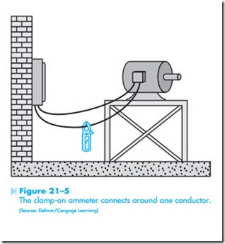
Many service technicians use the clamp-on type of AC ammeter. To use this type of meter, the jaw of the meter is clamped around one of the conductors supplying power to the load, Figure 21–5. The meter is clamped around only one of the lines. If the meter is clamped around more than one line, the magnetic fields of the wires cancel each other and the meter indicates zero.
This type of meter uses a current transformer to operate the meter. The jaw of the meter is part of the core material of the transformer. When the meter is connected around the current carrying wire, the changing magnetic field produced by the AC cur- rent induces a voltage into the current transformer. The strength of the magnetic field and its frequency determines the amount of voltage induced in the current transformer. Because 60 Hz is a standard frequency throughout the United States and Canada, the amount of induced voltage is proportional to the strength of the magnetic field.
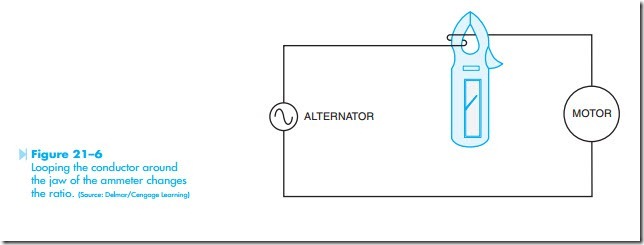
The clamp-on type ammeter can have different range settings by changing the turns ratio of the secondary of the transformer just as the in-line ammeter does. The primary of the transformer is the conductor the movable jaw is connected around. If the ammeter is connected around one wire, the primary has one turn of wire as compared to the turns of the secondary. The turn’s ratio can be changed in the same manner as changing the ratio of the CT. If two turns of wire are wrapped around the jaw of the ammeter, Figure 21–6, the primary winding now contains two turns instead of one, and the turns ratio of the transformer is changed. The ammeter will now indicate double the amount of current in the circuit. The reading on the scale of the meter would have to be divided by two to get the correct reading. The ability to change the turns ratio of a clamp-on ammeter can be very useful for measuring low currents.

