Autotransformers
The word auto means self. An autotransformer is literally a self-transformer. It uses the same winding as both the primary and secondary. Recall that the definition of a primary winding is a winding that is connected to the source of power, and the definition of a secondary winding is a winding that is connected to a load. Autotransformers have very high efficiencies, most in the range of 95% to 98%.
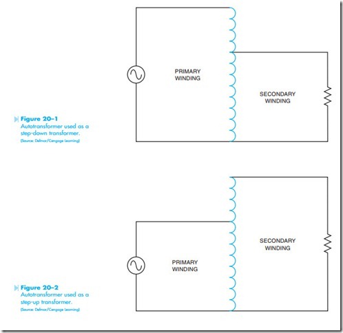
In Figure 20–1, the entire winding is connected to the power source, and part of the winding is connected to the load. In this illustration, all the turns of wire form the primary and part of the turns form the secondary. Because the secondary part of the winding contains fewer turns than the primary section, the secondary will produce less voltage. This autotransformer is a step-down transformer.
In Figure 20–2, the primary section is connected across part of a winding and the secondary is connected across the entire winding. In this illustration the secondary section contains more windings than the primary. This autotransformer is a step-up transformer. Notice that autotransformers, like isolation transformers, can be used as step-up or step- down transformers.
DETERMINING VOLTAGE VALUES
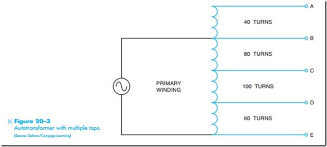
Autotransformers are not limited to a single secondary winding. Many autotransformers have multiple taps to provide different voltages as shown in Figure 20–3. In this example, there are 40 turns of wire between taps A and B, 80 turns of wire between taps B and C, 100 turns of wire between taps C and D,
and 60 turns of wire between taps D and E. The primary section of the windings is connected between taps B and E. It will be assumed that the primary is connected to a source of 120 volts. The voltage across each set of taps will be determined.
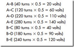
There is generally more than one method that can be employed to determine values of a transformer. Because the number of turns between each tap is known, the volts-per-turn method will be used in this example. The volts-per-turn for any transformer is determined by the primary winding. In this illustration, the primary winding is connected across taps B and E. The primary turns are, therefore, the sum of the turns between taps B and E (80 + 100 + 60 = 240 turns). Because 120 volts is connected across 240 turns, this transformer will have a volts-per-turn ratio of 0.5 (240 turns/120 volts = 0.5 volts-per-turn). To determine the amount of voltage between each set of taps, it becomes a simple matter of multiplying the number of turns by the volts-per-turn.


