3D flow features
Radial equilibrium and through-flow methods determine the meridional variations in the velocity field, but they assume that the turbomachinery flow field is axisymmetric. Cascade analysis and blade-to-blade computational methods consider the flow variations across the blade passages, but they neglect spanwise variations and radial flows (see Chapter 3). These two views of a turboma chine are very useful and both are essential in the design process, but in reality the flow field in all axial turbomachinery, to some degree, varies in the axial, radial, and tangential directions. The flow features that lead to fully 3D variations are discussed below.
Secondary flow
When a fluid particle possessing rotation is turned (e.g., by a cascade), its axis of rotation is deflected in a direction perpendicular to the direction of turning. The rotation of the fluid particles is known as vorticity, which is a vector quantity with a direction along the axis of rotation. The result of deflecting the axis of rotation is a component of vorticity in the direction of the flow streamlines, and whenever this occurs there are secondary flows.
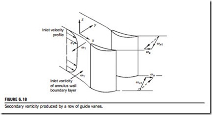
Consider the flow at inlet to the guide vanes of a compressor to be completely axial and with a velocity profile as illustrated in Figure 6.18. This velocity profile is nonuniform as a result of friction between the fluid and the wall; the vorticity of this boundary layer is normal to the approach velocity c1 and of magnitude
where z is distance from the wall.
The direction of ω1 follows from the right-hand screw rule and it will be observed that ω1 is in opposite directions on the two annulus walls. This vector is turned by the cascade, thereby
generating secondary vorticity parallel to the outlet stream direction. If the deflection angle ε is not large, the magnitude of the secondary vorticity ωs is, approximately,
A swirling motion of the cascade exit flow is associated with the vorticity ωs, which is in opposite directions for the two wall boundary layers. This generates simultaneous velocity variations in the spanwise and tangential directions that cannot be captured within two-dimensional models of the flow field (see Dixon, 1974).
The secondary flow structure in a blade passage is further complicated by the flow around the leading edge, as illustrated in Figure 6.19. The vorticity within the annulus wall boundary layer is split into two vortices as the flow stagnates. One vortex enters the blade passage near the pressure surface and the other vortex enters beside the suction surface. The vortex that starts beside the pres- sure surface is rapidly swept towards the suction surface by the cross-passage pressure gradient and forms what is known as the passage vortex. The other vortex, known as the counter vortex, sticks to the suction surface hub. In addition to these vortices, boundary layer fluid on the endwalls is swept from the pressure surface towards the suction surface. The result is a collection of highly rotational fluid on the suction surface near the hub and casing endwalls. This fluid leads to increased loss through viscous shear and mixing and forms a 3D wake structure downstream of the blades.
As well as increasing the loss, secondary flow affects the variation of exit flow angle from a blade row. The flow is overturned close to the endwalls, where the boundary layer fluid has been strongly turned by the cross-passage pressure gradients, and underturned some distance away from the endwalls, where the influence of the passage vortex is stronger. Hawthorne (1955) developed some of the first models of secondary flow in turbomachinery and showed how the exit flow angle distribution could be calculated using theoretical analysis. Figure 6.20 shows a comparison by Horlock (1963) between corrected exit flow angles calculated using such an analysis and
experimental results. The regions of underturning and overturning of the flow are predicted, although the magnitude of the variation is not the same as measured.
Note that secondary flow phenomena occur in all axial turbomachines. In turbines they can be stronger because of the large amount of flow turning and the high cross-passage pressure gradients that exist. However, in compressors, secondary flow effects are often more apparent and can have greater consequences because of the thick boundary layers on the annulus walls and the highly adverse pressure gradients in the streamwise direction.
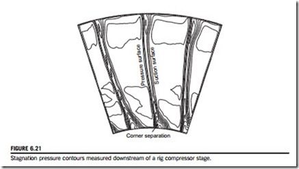
Figure 6.21 shows stagnation pressure contours measured downstream of a stator row in a compressor test rig. This shows the increased regions of loss near the endwalls beside the suction surfaces of the stator blades. In the case shown the aspect ratio of the blading is high and the majority of the wakes are still quite two-dimensional. In compressors, the low momentum fluid from the endwall boundary layers often separates on the suction surface due to the high level of diffusion there. This is known as a corner separation, which is also visible in Figure 6.21.
Figure 6.22 shows measured contours of normalized total pressure loss coefficient downstream of a turbine cascade trailing edge, from Pullan and Harvey (2008). Just downstream of the trailing edge, Figure 6.22(a), the wake is radial with a clear region of high loss around z/b 5 0.2. This is the passage vortex, which has carried inlet endwall boundary layer fluid from upstream of the leading edge. This vortex overturns the flow below it and underturns the flow above it. Further down- stream, Figure 6.22(b), this vortex combined with the other secondary flows present have distorted and twisted the wake.
Leakage flows
Turbomachinery blades require clearance gaps between the rotating and stationary components and these lead to leakage paths. Figure 6.23 illustrates the flow field over the tip of a rotor blade,
although the flow through a hub clearance gap of a stator blade cantilevered from the casing is similar. The leakage flow is driven by the pressure difference between the pressure surface and suction surface. The flow usually separates from the pressure side corner of the blade tip, which leads to a contraction of the flow area available. If the blade thickness is small compared to the tip gap, the leakage flow may not reattach (as is the case in many compressors). However, in thicker blades a separation bubble forms. The leakage flow then emerges as a high velocity jet at the suction surface tip, almost perpendicular to the free stream flow. The shear between the leakage jet and the free stream flow generates a tip leakage vortex, with a rotation axis aligned with the streamwise direc- tion. Losses are generated through viscous shear in the clearance gap as well as shear and mixing of the leakage jet with the free stream. Tip leakage losses typically account for around one-third of the total losses in a turbomachine (Denton, 1993). In addition, the leakage flow leads to blockage reducing the total mass flow and work transfer. In compressors, increased leakage significantly reduces the stability margin.
Note that some turbomachinery, particularly axial turbines, use a shroud. This is a band that covers and connects the blade tips (an example is shown in Figure 4.22). This prevents the tip leak- age flow described above. However, a leakage path still exists above the shroud from the high- pressure end to the low-pressure end (upstream to downstream in a turbine). Shrouded blades are also significantly heavier with greater centrifugal stresses.


