Thermostat Components
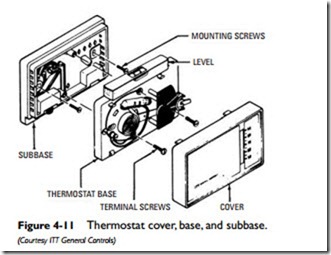
A thermostat consists of two basic parts: the base and the cover. A subbase can also be added to a thermostat to provide fan and various switch functions (see Figure 4-11).
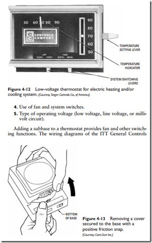
The cover protects the internal wiring of the thermostat base from dust, lint, and other possible contaminants. It also contains the temperature-setting lever, the system-switching levers, and the temperature indicator (see Figure 4-12).
The cover is secured to the base either with a positive friction snap or screws. If the former is the case, the cover can be removed by grasping the base with one hand and pulling it off with the other (see Figure 4-13). Screws may require the use of an Allen wrench (see Figure 4-14), which is usually supplied by the thermostat man- ufacturer and shipped with the unit.
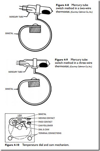
The base contains the internal wiring of the thermostat. Figure 4- 15 shows the back and front views of typical base wiring for the low-voltage thermostat illustrated in Figure 4-12. This is not the only possible way the base can be wired. How the base is wired will depend on the particular application. A few of the possible variations are illustrated by the thermostat base wiring diagrams in Figure 4-16. The many variations in wiring will depend on which combination of the following features is required by the installation:
1. Type of switch and switching action (snap-action or mercury bulb; spst or spdt contact).
2. Number of field wires (two, three, four, or five).
3. Type of anticipator (fixed heating, adjustable heating, fixed cooling).
thermostats and subbases shown in Figure 4-17 illustrate the variety of different switching combinations available.
Thermostat guards can be purchased to protect the thermostat from damage. This is particularly important in warehouses, stores, and other areas where there is a greater possibility of the thermo- stat being damaged. Some examples of how these guards are used are shown in Figure 4-18. Adapter plates (wall plates) are also available from thermostat manufacturers to cover electrical utility or junction boxes (see Figure 4-19)


