Temperature Control Circuits
The thermostat is the basic controller in the electrical control circuits used to operate a heating and/or cooling system. In systems using gas-fired heating equipment, there are three basic control circuits:
• Safety shutoff circuit
• Fan or circulator control circuit
• Temperature control circuit
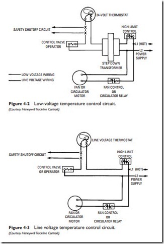
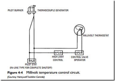
There are three basic types of temperature control circuits used in heating and cooling systems. These three basic circuits are as follows:
• Low-voltage control circuit
• Line voltage control circuit
• Millivolt control circuit
Typical wiring diagrams for these three temperature control circuits are shown in Figures 4-2, 4-3, and 4-4.
Thermostats
A thermostat is an automatic device designed to maintain tem- perature control. It accomplishes this function by reacting to temperature changes with adjustments of a controlled device such as a damper or valve motor or the automatic firing equipment (gas
burner, oil burner, or coal stoker) in space-heating furnaces and boilers. Because of its specific function, a thermostat is sometimes referred to as a temperature controller.
Thermostats can be classified on the basis of how they measure (or sense) temperature changes. The following devices are most commonly used to measure temperature changes:
• Bimetallic-strip sensing element
• Pressure-actuated sensing element
• Electrical resistance element
A bimetallic strip containing two dissimilar metals is probably the most widely used of these three temperature-measuring devices. Its operating principle is based on the different expansion and contraction rates of dissimilar metals. When two such metals are joined together in a bimetallic strip, the differences in expansion and con- traction rates will cause a bending movement as the temperature changes. This movement is utilized to open or close an electrical circuit between the thermostat and the controlled device in the heating and/or cooling system. The bimetallic-strip sensing element is used in either snap-action switch thermostats or mercury-switch thermostats.
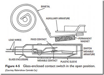
A thermostat that operates on the positive snap-action switching principle contains movable switch contacts. One of the contacts is
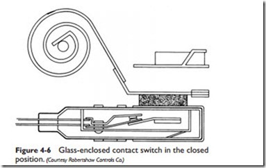
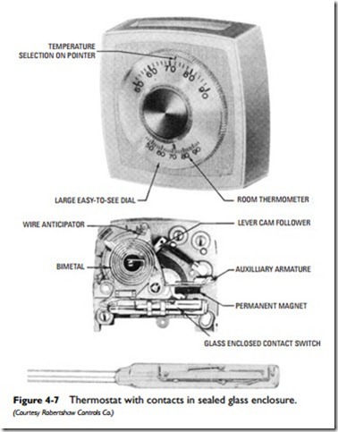
connected to a movable switch armature; the other is fixed in position. An auxiliary armature attached to a bimetal coil responds to temperatures induced by the expansion or contraction of a moving magnet (see Figure 4-5). The magnet, attached to the auxiliary armature, controls the movement of the switch armature. When the switch armature moves toward the magnet, it causes the contacts to close (see Figure 4-6).
On some thermostats, the switch contacts are hermetically sealed in a glass enclosure to protect them from dust or moisture. The thermostats illustrated in Figures 4-5, 4-6, and 4-7 are of this design.
A mercury-switch thermostat contains fixed contacts sealed in a mercury-filled tube. The tube is attached to the end of a spiral bimetal element. When the temperature changes, the bimetal element tilts the tube and causes the mercury to shift its position, causing a definite opening and closing of the electrical circuit.
A two-wire thermostat using the mercury tube switch method is illustrated in Figure 4-8. A drop in temperature causes the mercury switch to complete (close) the circuit. The circuit is broken (opened) on a rise in temperature.
Figure 4-9 illustrates the application of the mercury tube switch method in a heating and cooling thermostat. A common terminal wire runs along the bottom of the mercury tube. Mercury can make
contact between either the heating or cooling terminals, but not both at the same time.
Sealing the contacts in a mercury-filled tube provides excellent protection against contamination; however, care must be taken to properly level the base when mounting the unit because the position of the tube determines the switching action.
On either the snap-action or mercury-switch thermostat, the temperature setting of the thermostat can be changed by rotating the temperature dial. This device, acting through the cam, causes the bimetal coil to rotate through its mounting post to carry the temper- ature setting (see Figure 4-10).
Another temperature-measuring device used in thermostats is the pressure-actuated sensing element. A liquid, gas, or vapor with a high coefficient of expansion is used to activate a bellows connected to a snap mechanism. A rise in temperature causes an expansion in the volume of the liquid, gas, or vapor. This expansion is transferred to the bellows, which activates the snap mechanism. See Remote Bulb Thermostats later in this chapter for additional details.
An electrical-resistance sensing element consists of a coil of wire with an electrical resistance that changes in direct proportion to temperature changes. This type of sensing element is commonly used in electronic controllers.
A thermocouple device consisting of two dissimilar electrical wires welded together at one end also serves as a temperature-sens- ing element in some thermostats. Temperature changes at the
welded juncture of the two wires cause electrical changes in the control circuit, which operates a regulatory device.
Related posts:
Incoming search terms:
- circuit diagram for temperature control using mercury thermostat
- THERMOSTAT TEMP REGULATOR CIRCUIT
- hvac heater controlling circuit with thermostat humidistat
- hvac temperature control circuit
- temperature control using bimetallic strip
- temperature control using mercury thermostat
- uses of a thermostat in a control circuit
