Natural Vacuum Systems
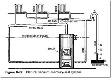
Any standard one- or two-pipe steam system may be converted into a natural vacuum system by replacing the ordinary air valve with a mercury seal or connecting thermostatic valves to the radiator return outlet on radiators and providing a damper regulator on coal-burning boilers adapted to vacuum working. The mercury-seal system is shown in Figure 8-29.
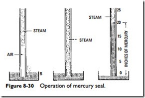
A mercury seal is virtually a barometer, consisting, as shown in Figure 8-30, of a tube (A) that dips just below the surface of the mercury in a cup (B). When the steam is raised in the boiler to pressures above atmospheric, it drives all air out of the system, the air leaving by bubbling through the mercury in cup B.
If the fire is allowed to go out, the steam will condense and pro- duce a vacuum, provided all pipe fitting has been carefully done and the valve stuffing boxes are tightly packed.
In Figure 8-29 the loop at C prevents water from being carried over into the seal pipe when purging the system of air. If air should again enter the system, it can be expelled by raising the steam pressure above atmospheric. In very cold weather, the system can be operated at pressures above atmospheric by closing valve D. When fires are banked for the night, valve D may be opened and the system worked as a vacuum system. The flexibility of vacuum systems is in sharp contrast with low-pressure systems, where steam
disappears from the radiators as the temperature drops below 212°F. According to weather demands, the radiators may be kept at any temperature from, say, 150 to 220°F.
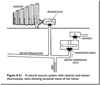
Another method of maintaining a natural vacuum is by using thermostatic valves instead of a mercury seal. A thermostatic valve has an expansion element that operates to close the valve when heated by hot steam and to open the valve when chilled by the relatively cold condensate.
The two kinds of thermostatic valves used are the single-unit (or retainer) valves and two-unit, or combined retainer and air-check, valves sometimes called master thermostatic valves.
Figure 8-31 shows the details of a master thermostatic valve, consisting of a thermostatic unit and an air check. The thermostatic unit has an expanding element, the air check, consisting of a group seat poppet check valve that is practically airtight and therefore will retain the vacuum within the system for a considerable length of time. The air check operates when excess pressure is generated in the boiler to purge the system of air, the check at other times remaining closed.
The thermostatic valve remains open while the system is being purged of air and condensation but closes when steam enters the valve chamber—it retains vacuum in the air line.
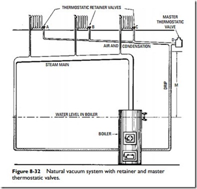
Figure 8-32 shows the operation of the natural vacuum system with retainer and master thermostatic valves. Individual thermo- static retainer valves A, B, and C are placed in the outlet of each radiator, which pass air or water but close to steam. At the end of the air line is a master thermostatic valve (D), which operates when the system is purged of air by excess pressure.
The drip should be proportioned to prevent water entering the air line in case of high vacuum in such a manner that the vertical distance M between the water level in the boiler and the lowest point of the air line is not less than 2 ft for each inch of vacuum to be carried in the system.
The successful operation of natural vacuum systems depends largely on efficient damper regulators on coal-burning boilers (i.e., efficient draft control), for unless the fire is held in proper check, the pressure will rise and break the vacuum. This can waste fuel, for there may be sufficient heat in the boiler to supply steam to the system with a 5- or even 10-in vacuum and hold that heat in the system for hours.
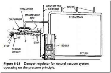
Automatic damper regulators are designed to act by pressure, temperature, or a combination of these two. Figure 8-33 shows a regulator that acts on the pressure principle. It consists of a diaphragm connected at B to a lever having its fulcrum at A and having a weight W free to slide along a slot between the stops.
In starting, the weight is placed on the left side of the lever as shown (Figure 8-33). This tilts the lever (position LF) and opens the
damper. The weight is adjusted by the stop so that sufficient pressure is produced to clear the system of air before the regulator tips to position L‘F‘ (shown in dotted lines) and closes the damper.
The regulator is gradually closing as the pressure comes on. When the regulator is entirely closed, the weight slides to the right and remains in this position until the vacuum in the system becomes strong enough to gradually open the damper—just enough to maintain a vacuum.
In the morning, the regulator may be set to the open position from the floor above by the pull chain M. This generates pressure and purges the system of any air that might have accumulated; then the regulator weight automatically goes to the vacuum side of the regulator and maintains the vacuum heat until more fuel is required or
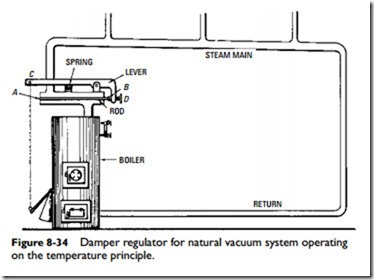
further regulation is necessary. Temperature controls or damper regulators that depend on temperature changes for their operation may also be used (Figure 8-34). Since the temperature of steam increases with the pressure, evidently the expansion and contraction of a rod exposed to the steam can be made to operate the damper.
Figure 8-34 shows the construction of a typical thermostatic regulator. The expansion element or rod is fastened at A in a closed cylindrical chamber through which steam from the boiler passes to the main. The end B is free to move, passing out of the chamber through a stuffing box. The motion of the rod is considerably magnified by the bell crank lever, which is connected to the damper by a chain attached at C.
In operation, as the pressure of the steam rises, so does its temperature; the rod (which is made of a metal having a higher coefficient of expansion than that of the cylindrical chamber) expands, and its free end, B, moves to the right, thus causing end C of the lever to descend, closing the damper.
When the pressure falls, the rod contracts, and the spring that keeps the bell end in contact with the rod causes end C of the lever to rise and open the damper.
The lever will assume some intermediate position in actual operation, thus holding the steam at some predetermined pressure, which may be varied by means of the screw adjustment (D).
The major objection to regulation by temperature is that there is no provision for securing excess pressure to purge the system of air in starting. This must be done by hand control of the damper. This objection can be overcome by the method of combined pressure and temperature regulation, which employs pressure for starting and temperature for running. In starting, the thermostatic portion of the regulator is closed off from the systems during which pressure is generated sufficient (about 1 pound) to purge the air from the system. After purging, the regulator automatically opens a valve to the thermostatic position, which then maintains the temperature desired, its range embracing both vacuum and low-pressure operation.
