CIRCUIT OPERATION
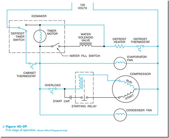
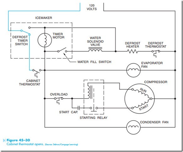
In the first stage of operation, the circuit is shown during the freeze cycle, Figure 45–29. The cabinet thermostat and defrost heater thermostat are both closed. At this point, several circuit paths exist. One circuit is completed through the timer motor, defrost heater, and defrost thermostat. A circuit is completed through the evaporator fan, condenser fan, and the run winding of the compressor. If the cabinet thermostat should open, as shown in Figure 45–30, the timer motor also stops.
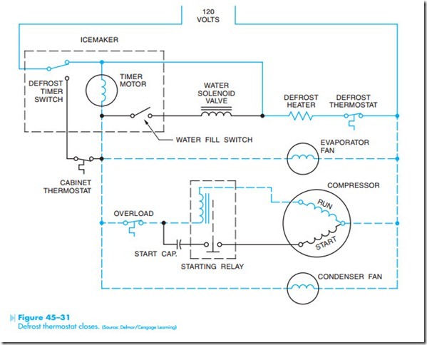
After 9.6 hours of timer motor operation, the defrost timer switch changes position and completes the circuits shown in Figure 45–31. The defrost heater is now connected directly to the power line, which permits it to warm the evaporator and melt accumulations of frost. A current path also exists through the timer motor to the evaporator fan, compressor run winding, and condenser fan. It is this circuit path that permits the timer motor to continue operation if the defrost thermostat should open its contacts. The timer motor must continue to run, or the defrost cycle cannot be completed. Note that
the winding of the timer motor has a much higher impedance than the run winding of the compressor. This permits almost all the voltage to be dropped across the timer motor and very little to be dropped across the evaporator fan, compressor run winding, and condenser fan. At this time, the timer motor will operate, but the other motors will not. The defrost cycle lasts for approximately 21.5 minutes.
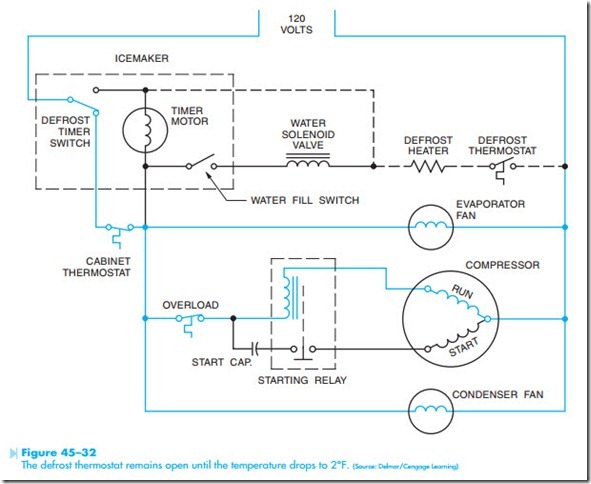
At the end of the defrost cycle, the defrost timer switch changes back to its normal position. Because
the defrost thermostat opens its contacts at approximately 70°F and does not reclose them until the evaporator reaches about 2°F, it is normal for these contacts to be open at the end of the defrost cycle, Figure 45–32. During this time, the timer motor is turned off.
Under normal conditions, the ice maker activates after 2 hours of timer motor running time. Figure 45–33 shows the condition of the circuit near the end of the ejection cycle. The cam-operated water fill switch has closed and now completes a circuit through the water solenoid valve, defrost
heater, and defrost thermostat. Note that if the cabinet thermostat should open during the water fill cycle, the cycle will be interrupted until the cabinet thermostat again closes.
Because the timer motor is used to operate both the ice maker and defrost cycle, it is possible for the ice ejection cycle to occur during the defrost cycle, Figure 45–34. Notice that a parallel current path exists through both the timer motor and water solenoid valve. If the defrost thermostat should open while the water valve switch is closed, the same current path is provided through the evaporator fan, compressor run winding, and condenser fan for both the timer motor and water solenoid valve. This permits the tray to dump the ice and refill with water.


