Purging Air from the System
Built-in or externally installed air separators are designed to separate air from the water in an operating boiler and vent it either into an expansion tank or to the atmosphere through an automatic air vent.
Air can also be removed from a heating system by purging it from the piping connections to the boiler. This type of purging is standard when the system is being filled with water during setup. Purging instructions are usually included in the owner’s manual or the manufacturer’s installation guide.
Expansion Tanks
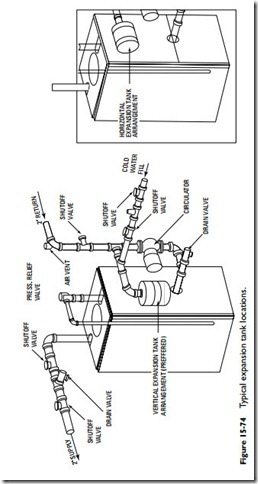
A hot-water heating system is completely filled with water. When the water is heated, it expands in volume by as much as 5 percent. The function of the expansion tank in a hot-water heating system is to provide a space to accommodate the increased volume of water. There are two types of expansion tanks: steel tanks and diaphragm tanks (Figure 15-74). Both are described in considerable detail in Chapter 10, “Steam and Hot-Water Line Controls” in Volume 2.
Air Supply and Venting
An adequate air supply must be provided for combustion to boilers that are fired by gas, oil, or coal, and the products of combustion must be vented to the outside atmosphere.
Combustion air is normally supplied through venting ducts or openings in the walls, if the appliance relies on natural ventilation for its air. The requirements for the air supply will depend upon the location and enclosure of the boiler.
Boilers installed in unconfined areas usually obtain adequate air for combustion by means of normal infiltration. However, normal air infiltration will be inadequate for this purpose if the construc- tion of the structure is unusually tight. Under these circumstances, provision must be made for the entry of additional air from out- side the building. Unobstructed openings with a total free area of not less than 1 in2 per 5000 Btu/h of the total input of the boiler are necessary to provide an adequate air supply for combustion purposes.
Some boilers are installed in boiler rooms or enclosures supplied with combustion air from inside the structure. The air supply must enter and leave the boiler room through two openings in an interior
wall or door. One opening is located near the ceiling, the other opening near the floor. Each opening should have a free area of not less than 1 in2 per 1000 Btu/h of the total input of the boiler.
If a boiler is located in a boiler room or similar enclosure that receives its air supply from outside the building, the two air openings are located on an exterior wall. Each opening must have a free area of not less than 1 in2 per 4000 Btu/h of the total input of the boiler.
The products of combustion must be vented to the outside atmo- sphere. In order to accomplish this, the boiler must be connected to a suitable venting system, which should include a flue pipe and a chimney or stack of adequate size and capacity.
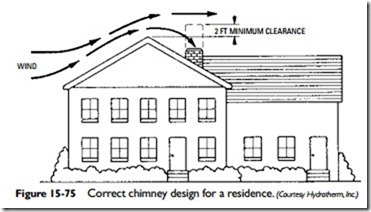
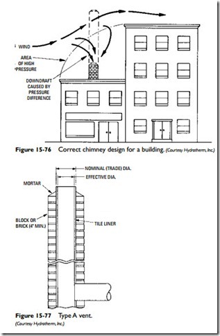
The chimney height is usually governed by the height of the structure. As a general rule-of-thumb, the chimney should extend beyond the high-pressure area caused by the passage of 10 ft of the flashing. If the chimney is too short, it will not extend beyond the high-pressure area caused by the passage of winds over the structure. As a result, a downdraft caused by the pressure difference in the high-pressure area will push air down into the chimney, which will block the escape of flue gases and interfere with the combustion process. Figures 15-75 and 15-76 illustrate these principles. The correct chimney height is shown by the dotted lines.
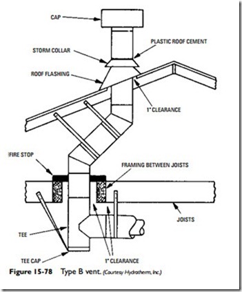
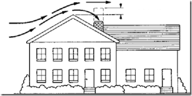 Figure 15-77 shows a type of chimney construction referred to as a Type A vent. This chimney can be either masonry or factory-built construction, but it must be designed and constructed in accor- dance with the standards set forth in national codes. Type A vents are suitable for venting of all gas appliances. These are the only
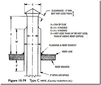
vents suitable for venting oil-burning equipment. Gas-fired boilers that produce temperatures at the draft diverter not in excess of 550°F may also use a Type B vent (Figure 15-78), which employs a double-wall metal vent pipe. A Type C vent (Figure 15-79) is used to vent gas appliances in attic installations.
The boiler should be located so that the length of flue pipe con- necting the boiler (or draft diverter) to the chimney is as short as possible. Additional information about chimneys and flues is con- tained in Chapter 11, “Gas Furnaces.”
