Pressure-Reducing Valves
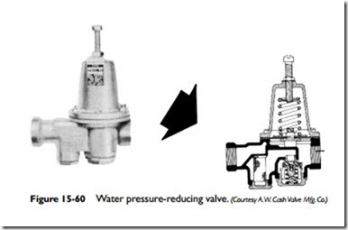
Most hot-water heating systems are equipped with a water pressure-reducing valve designed to feed water into the boiler automatically when the pressure in the system drops below the valve setting. When the pressure returns to the minimum pressure setting, the valve automatically closes. Thus, the function of a water pressure-reducing valve is to keep the system automatically filled with water at the desired operating pressure (Figure 15-60). These valves are also referred to as pressure-reducing boiler feed valves, water pressure- reducing fill valves, or feed water pressure regulators. Regardless of what they are called, their function remains the same: to deliver water to the boiler at the required pressure. To perform this function,
they are always installed in the cold-water supply line. If they are part of a combination pressure-reducing and pressure relief valve (dual control), the pressure relief part of the combination valve is always located between the boiler and the pressure-reducing part.
A manually operated feed valve was used on older hot-water heating systems to provide the same function as the automatic water-pressure-reducing valve. On these older systems, the manu- ally operated feed valve should be partly opened and water added to the boiler when the movable (white or red) arrow on the altitude gauge drops below the setting of the stationary (black) arrow (see Altitude Gauges in this chapter).
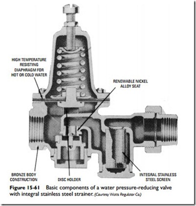
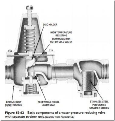
Some pressure-reducing valves are equipped with a built-in check valve in the supply inlet to prevent a backflow of contami- nated boiler water into the domestic water supply. This backflow drainage of boiler water generally occurs when the supply pressure falls below the feeder valve setting. Not only can this drainage cause possible damage to the boiler, it can also contaminate the domestic water supply. Some pressure-reducing valves are also equipped with integral strainers to trap foreign matter that may clog the valve. The strainer screen should be removed for cleaning at the beginning of each heating season. This can be done by removing the bottom plug from the strainer and withdrawing the screen. Clean and carefully replace screen and plug.
The principal components of a water-pressure-reducing valve are shown in Figure 15-61. This particular valve is constructed with an integral strainer. It is also possible to use separate units in combina- tion, as Figure 15-62 illustrates. The two units are joined by a short threaded connection. A typical installation in which a water- pressure-reducing valve is used is shown in Figure 15-63.
As mentioned previously, a water-pressure-reducing valve should be installed in the water supply line to the boiler. It should also be installed at a level above the boiler and in a horizontal position. Before installing the valve, flush out the supply pipe to clear it of chips, scale, dirt, and other foreign matter that could interfere with its operation. Install a shutoff valve ahead of the regulator, and then connect the supply line to the inlet (usually marked “in” on the valve casting).
To fill the system, open the shutoff valve located ahead of the pressure-reducing valve. Water will flow into the system until it is full and under pressure. The shutoff valve must always be kept open when the system is in operation.
Water-pressure-reducing valves are usually set by the manufac- turer to feed water to the boiler at approximately 15 lb of pressure.
This pressure setting is sufficient for residences and houses up to a three-story building in size. For higher buildings in which the pres- sure may not be sufficient to lift the water to the highest radiator, it may be necessary to reset the water-pressure-reducing valve for higher pressure. To do this, calculate the number of feet from the regulator to the top of the highest radiator. Multiply this by 0.43 and add 3 lb. This will give the pressure needed to raise the water to the highest radiator and keep it under pressure. Loosen the locknut on the valve, and turn the adjustment screw clockwise slowly until the gauge indicates the pressure calculated. When the desired pres- sure is obtained, tighten the locknut.


