Combination Valves
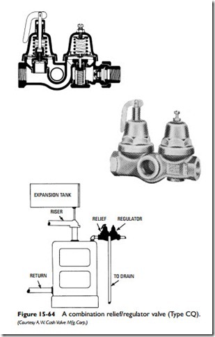
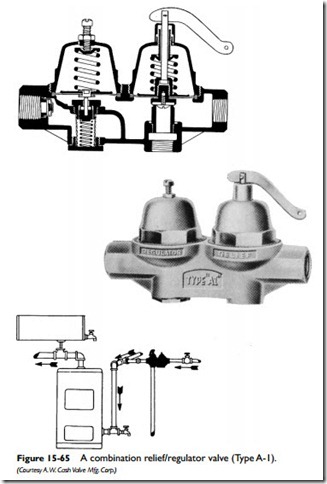
Combination valves (also called dual unit valves or dual control valves) are designed for use in hot-water space heating systems. They combine a pressure-reducing/pressure-regulating valve and a positive relief valve in one body (Figures 15-64 and 15-65). Sometimes an integral bypass valve is also included in the same unit.
The purpose of a combination valve is to provide pressure regulation and safety control and to reduce boiler pressure and ensure automatic filling when conditions warrant. The valve is installed on the supply line of a boiler with the relief-valve section closest to the boiler.
The regulator side of the combination valve is designed to reduce the incoming water supply to the boiler to the required 14-psi operating pressure for a one-, two-, or three-story house. The pressure
in the system builds up due to thermal expansion when the boiler is fired. Under normal operating conditions, the expansion tank will absorb the additional pressure. However, if the expansion tank is waterlogged or if the system has no expansion tank, the relief side of the valve will open at 23 psi and drop the pressure back to within safe limits. If the pressure should drop below 14 psi, the reg- ulator will open again and automatically refill the system. A built- in check valve prevents the backflow of contaminated boiler water into the potable water supply.
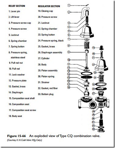
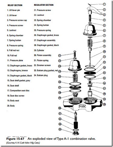
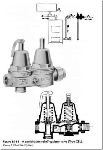
Exploded views of combination valves are shown in Figures 15-66 and 15-67. The Cash-Acme Type CBL Valve (Figure 15-68) differs from the other two by having a built-in bypass valve. In all other respects, it is similar to the others except that it should be installed as close as possible to the top of the boiler (using close nipples). The principal advantages of having the bypass valve included are:
1. It allows rapid filling of the system.
2. It permits an easy high-pressure test for leaks and system purging.
3. It passes first filling dirty water around the valve seat, ensuring a clean, good seating surface.
4. It permits the use of a wide opening, small seated regulator that prevents wire drawing and rapid wearing of the seat.
The most common types of problems encountered when using combination valves are the following:
3. Water escapes from a weep hole on top of the regulator.
4. Water escapes from feeder side of the combination valve.
5. Foreign matter collects on the seat of the relief or regulator section of the valve.
Some of the problems listed above (particularly the first two) may not be the fault of the valve itself. For example, a dripping relief valve can be caused by an expansion tank being completely filled up with water, an undersized expansion tank, or a leak in the coil of a tankless or indirect water heater installed in the boiler. These possibilities should be checked before attempting to service or repair the valve. The procedures are outlined in this chapter.
If, by process of elimination, the problem can be traced to the valve, try tapping the side of the valve with a wrench. Sometimes a piece of foreign matter becomes lodged and causes the regulator piston to stick. A sharp tap with a wrench may dislodge it and allow the valve to function properly.
Foreign matter such as dirt, pipe scale, or chips often cause a valve to malfunction by lodging on a seating surface, or nicking or chipping the surface. Valve manufacturers often provide replace- ments or instructions for field servicing and repairing. The latter should be attempted only by a skilled and experienced worker with the proper tools and gauges.
Water seeping from the regulator “weep hole” or from the feeder side of a combustion valve is usually an indication that there is a rupture or leak in the diaphragm. Follow the procedures described in the preceding paragraph for repairing the valve. An occasional flushing of the relief side of a combination valve will reduce the possibility of the type of lime or scale buildup that can cause the valve to fuse shut.
