TESTING THE TRIAC
The triac can be tested with an ohmmeter. To test the triac, connect the ohmmeter leads to MT2 and MT1. The ohmmeter should indicate no continuity. If the gate lead is touched to MT2, the triac should turn on and the ohmmeter will indicate continuity through the triac. When the gate lead is released from MT2, the triac may continue to conduct or turn off depending on whether the ohmmeter sup- plies enough current to keep the device above its holding current level. This tests one half of the triac. To test the other half of the triac, reverse the connection of the ohmmeter leads. The ohmmeter should again indicate no continuity. If the gate is touched again to MT2, the ohmmeter should indi- cate continuity through the device. The other half of the triac has been tested. The following step-by-step procedure can be used to test a triac.
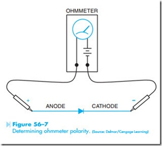
1. Using a junction diode, determine which ohmmeter lead is positive and which is negative. The ohmmeter will indicate continuity only when the positive lead is connected to the anode and the negative lead is connected to the cathode, Figure 56–7.
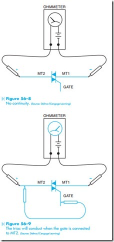
2. Connect the positive ohmmeter lead to MT2 and the negative lead to MT1. The ohmmeter should indicate no continuity through the triac, Figure 56–8.
3. Using a jumper lead, connect the gate of the triac to MT2. The ohmmeter should indicate a forward diode junction, Figure 56–9.
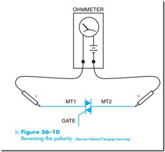
4. Reconnect the triac so that MT1 is connected to the positive ohmmeter lead and MT2 is connected to the negative lead. The ohmmeter should indicate no continuity through the triac, Figure 56–10.
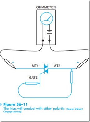
5. Using a jumper lead, again connect the gate to MT2. The ohmmeter should indicate a forward diode junction, Figure 56–11.


