BASIC CIRCUIT CONNECTIONS
Op amps are generally used in three basic ways. This is not to say that op amps are used in only three circuits, but that there are three basic circuits that are used to build other circuits. One of these basic
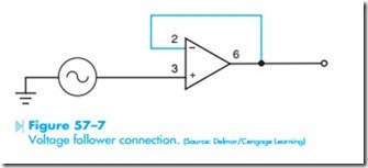
circuits is the voltage follower. In this circuit, the output of the op amp is connected directly back to the inverting input, Figure 57–7. Because there is a direct connection between the output of the amplifier and the inverting input, the gain of this circuit is 1. For instance, if a signal voltage of .5 volts is connected to the noninverting input, the output voltage will be .5 volts also. You may wonder why anyone would want an amplifier that does not amplify. Actually, this circuit does amplify something. It amplifies the input impedance by the amount of the open loop gain. If the 741 has an open loop gain of 200,000 and an input impedance of 2 megohms, this circuit would give the amplifier an input impedance of 200K X 2 megohms or 400,000 megohms. This circuit connection is generally used for impedance matching purposes.
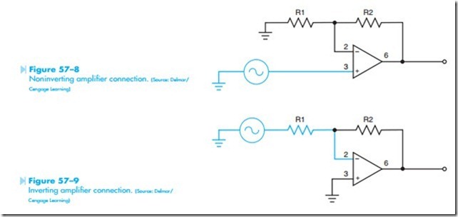
The second basic circuit is the noninverting amplifier, Figure 57–8. In this circuit, the output voltage is the same polarity as the input voltage. If the input voltage is a positive-going voltage, the output will be a positive-going voltage at the same time. The amount of gain is set by the ratio of resistors R1 + R2/R1 in the negative feedback loop.
The third basic circuit is the inverting amplifier, Figure 57–9. In this circuit the output voltage will be opposite in polarity to the input voltage. If the
input signal is a positive-going voltage, the output voltage will be negative-going at the same instant in ime. The gain of the circuit is determined by the ratio of resistors R2 and R1.


