SLAB CONSTRUCTION INSULATION PROBLEMS
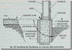
Houses and buildings constructed on concrete slab are in di rect contact with the ground. Unless they are properly insulated, the slab can become extremely cold and damp. Some form of insulation should be placed between the slab and the ground be fore the concrete is poured (Fig. 23). Insulation can be added to an existing structure by excavating around the edges of the foundation to a level below the frost line, and adding 2 inches of waterproof insulating material to the sides of the slab (Fig. 24).
INSTALLING BATTS AND BLANKETS
Batt or blanket-type insulation is usually available faced with paper on both the front and back surfaces. Paper flanges extend ing along both sides of the batt or blanket are used for nailing or stapling the insulation to studs or joists.
Some batts or blankets are manufactured with a vapor barrier on one side, usually in the form of asphalt-impregnated paper. When this is the case, the surface with the vapor barrier should be installed so that it faces inward toward the heated rooms and spaces. For example, when installing insulation between top floor ceiling joists, place the insulation so that the surface with the vapor barrier faces downward toward the heated occupied rooms and spaces below.
When the batt or blanket insulation is installed directly over an insulating board panel ceiling, ordinary wood lath spaced approximately 6 inches on centers should be laid across the furring strips to support the insulation.
Insulation should be secured in place by tacking or stapling through the paper flanges extending along the sides of the batt or blanket insulation to the frame members. Space fasteners on 6 inch centers. Where lath is to be applied after insulation has been installed, fasteners sufficient only to hold the insulation in place temporarily need be used. Overlap the flanges on the face of each stud or joist to be certain there will be no break in the vapor barrier.
Insulation should be placed under the bridging between joists on ceilings if there is sufficient clearance. If there is insufficient clearance, cut the insulation and fit it around the bridging, but extend the vapor barrier under it. Stuff handfuls of insulation in
the spaces in the bridging. Remember to place the vapor barrier so that it faces down toward the occupied spaces below.
Start tacking or stapling insulation at the plate at the top of walls and work down toward the floor. Compress the insulation so that it extends around the back of pipes, ducts, outlet boxes, electrical receptacles, and other structural components that must remain exposed to the room (i.e. the interior) side of the walls. If it is not possible to extend the batt or blanket-type insulation behind them, then cut (or tear) the insulation and work it around the back, making certain the fit is as tight as possible. Be particu larly careful to refit the vapor barrier so that there is no break.
Floors can be protected with a vapor barrier over the sub floor or between the floor joists and the subfloor. Waterproof roofing paper should be placed over the ground in foundation crawl spaces and extended up the insides of the exterior founda tion walls. The exterior walls of crawl spaces should also be in sulated with 2 to 3 inches of insulation. This will reduce the amount of cold air seepage entering the foundation crawl space area.
APPLYING BLOWN INSULATION
Blown insulation (not batt or blanket-type insulation) is recommended for insulating the exterior walls of existing struc tures. It requires the use of pneumatic equipment , and the knowl edge of where to drill access holes in the exterior walls and how much insulation to use to completely fill each stud space.
The equipment and tools required for blown insulation are:
1. A blowing machine with hoses,
2. Electric drills,
3. Circular saws,
4. Screwdrivers.
The circular saws should have teeth set for wood cutting. The screwdrivers are used for removing plugs from the saws (if not self-ejecting).
The insulation when blown into the walls and attic spaces with compressed air, fills every space with heat resistant material. This method is the only practical way of insulating structures already constructed, whether of wood, brick or stone veneer , or stucco.
The insulation is usually blown into the walls at 2 lbs. per sq. in. pressure or less. This pressure gives a firm, even pack which assures maximum thermal efficiency. Furthermore , it puts the material under an initial compression so that any subsequent vi bration or building movement will not cause the insulation to settle, but rather to expand and thus retain its full insulating value.
The insulation work, for the most part , is done from the out side of the building with a minimum of litter, dust or disturbance inside the building.
The openings for blowing are made near the top of wall panels ,and the insulation is installed by inserting the nozzle and blowing which comes from the blowing machine, into each hole and blow ing the material into the panel.
Before starting to blow the insulation into the interior spaces of the wall, soundings should be made with a plumb bob to lo cate cross framing. Where such framing is found, additional openings are made to assure that all spaces will be filled.
For the third story of houses having one or more rooms above the ceiling joists of the second floor, it is necessary to get between the roof and the walls of the upper story room and insulate the side walls (knee walls) of the room from behind. This is done by boarding up the back of the studs with insulating board or by nailing diamond crosscord paper or a similar material across the back of the studs, and blowing behind it. It may be necessary to make an opening in the roof large enough to allow workmen to enter. The entire ceiling, including the portion from the wall line of the eaves to the walls of the third-story room, is insulated by blowing.
All portions around windows should be insulated thoroughly, as considerable air infiltration takes place around window framing.
In the case of open joists on unfloored attics, the man operat ing the nozzle stands on the joists and sprays the material to the desired thickness between the joists. Because these areas are not blown under pressure, there is no settlement problem. Therefore the one objective is to lay the material as evenly as possible in order to eliminate extra labor of leveling or screening by hand.
If the attic is floored, it is necessary to remove a few boards and insert the hose between each pair of joists, pushing the hose in as far as necessary to fill the space to the eave line. The material is then blown and as the space fills up to the required depth, the hose is slowly withdrawn.
It is recommended,as a general practice, that the size of holes made for blowing the insulation material be no greater than 3 inches, and no less than 2 inches in diameter. A 2Y2 inch diam eter hole is sufficient to take the entire output from a 2Y2 inch diameter hose.
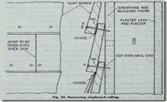
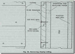
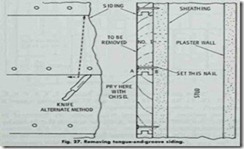
Removing building materials from the exterior walls in order to drill holes for blowing the insulation requires the skill of an experienced worker. Each type of construction (e.g. clapboard, wood siding shingles, brick veneer, etc.) presents a different prob lem. For example, Figs. 25, 26, 27 and 28 illustrate the problems involved in removing clapboard, siding joined with a shiplap, siding joined with a tongue-and-groove, and wood siding shingles.
A shingle should be removed by inserting a shingle ripper under the course above the shingles to be removed (Fig. 29). The upper and lower course of nails is cut by hammering the ripper downward and upward. Then insert the ripper under the shingle to be removed and cut two sets of nails, upper and lower, by pulling or hammering downward on the ripper.
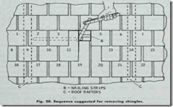
Removing shingles should be done with a definite sequence in mind. This is illustrated in Fig. 30. For example, if five shin gles are to be removed from the top row, the number should start at the left. Shingle No. 1 remains in the roof; shingles Nos. 2, 3, 4, 5, and 6 are removed; and No. 7 remains in the roof. Shingles 1, 7, 8, 15, 16 and 22 remain in place. Remove 2, 3, 4, 5, 6, 9,10, 11, 12, 13, 14, 17, 18, 19, 20 and 21 for opening (more if necessary ) .
Two methods for removing brick veneer are illustrated in·Fig. 31. Care must be taken to match the color of the old mortar when refilling the hole.
The method of blowing exterior stud walls, after the removal of that part of the outside surface essential for the preparation
of holes for blowing, is usually a standard procedure. It is recom mended that no greater vertical height than 7 feet be blown from any one wall opening. Blowing upward from any opening should not exceed a height of 2 feet.
![Fig.-23.-Insulating-concrete-slab._t[2] Fig.-23.-Insulating-concrete-slab._t[2]](http://machineryequipmentonline.com/hvac-machinery/wp-content/uploads/2020/04/Fig.-23.-Insulating-concrete-slab._t2_thumb.jpg)
![Fig.-28.-Removing-wood-shingle-sidin[1] Fig.-28.-Removing-wood-shingle-sidin[1]](http://machineryequipmentonline.com/hvac-machinery/wp-content/uploads/2020/04/Fig.-28.-Removing-wood-shingle-sidin1_thumb.jpg)
![Fig.---29.---Removing---a---shingle-[1] Fig.---29.---Removing---a---shingle-[1]](http://machineryequipmentonline.com/hvac-machinery/wp-content/uploads/2020/04/Fig.-29.-Removing-a-shingle-1_thumb.jpg)
![Fig.-31.-Two-methods-used-for-removi[1] Fig.-31.-Two-methods-used-for-removi[1]](http://machineryequipmentonline.com/hvac-machinery/wp-content/uploads/2020/04/Fig.-31.-Two-methods-used-for-removi1_thumb.jpg)