Service gauge manifold
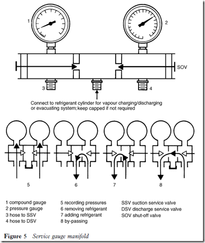
This is also called a system analyser. It consists of a manifold on the top of which are mounted two pressure gauges (Figure 5). Underneath the manifold
are three external hose connections, and at either side of the manifold is a shut-off valve. These valves seat to a position at each side of the centre hose connection, and when closed (turned fully clockwise) will prevent passage of vapour to the centre hose. Current manifold designs may include other features, but in this instance the standard model is illustrated.
A colour code has been introduced for the pressure gauges, hoses and shut- off valves.
The left hand pressure gauge is known as a compound gauge because it will record both positive and negative pressures, since the gauge is cali- brated to read zero at atmospheric pressure. The gauge pressure range is from 30 in Hg to 0 psi (0.9 to 0 bar) for pressures below atmospheric pressure, and from 0 to 250 psi (0 to 10.7 bar) or more for those above. This gauge is coded blue.
The right hand gauge is called a pressure gauge. It only records pressures above atmospheric, from 0 to 500 psi (0 to 35 bar). This gauge is coded red.
The hoses are also colour coded to correspond to the gauges and shut-off valves. The blue hose should be connected to the compound gauge, the yellow to the centre connection and the red to the pressure gauge.
When the manifold is assembled it is not necessary to open the valves. Pressure will be recorded as soon as the system pressure is passed to the hose after setting the compressor service valve. When either valve is opened, and
assuming pressure is available from the system, it will pass to the centre hose. It is advisable to keep the centre hose plugged at all times, or the centre connection capped when the hose is removed.
With the centre connection capped and both valves open, it will be seen that the pressures will equalize on both gauges. When both valves are closed and the centre connection is capped, it will be seen that both negative and positive pressures can be recorded when the compressor service valves are set to operating positions, assuming that the system is designed to operate in such a manner.
The function of the valves on the manifold is shown in Figure 5.
The service gauges are a vital part of a service engineer’s equipment. They are invaluable for performing service operations or diagnosing faults, which will be dealt with later.

