Installing Radiators
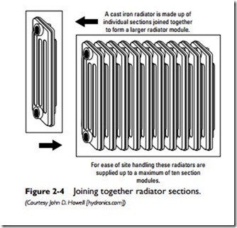
A cast-iron radiator is constructed by joining together a number of individual sections (see Figure 2-4). The number of sections used depends on the heating requirements for the room or space. For purposes of on-site handling, these radiators are supplied up to a
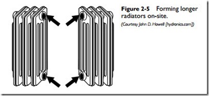
maximum of 10 section modules. Additional sections can be joined together on site to form longer radiators (see Figure 2-5). The procedure used to join the sections will depend on whether the nipples are threaded or smooth and beveled.
Joining Threaded Radiator Sections
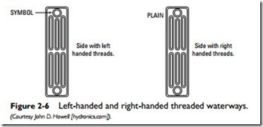
In older cast-iron radiators, each section has a pair of 11⁄4-inch-diameter threaded openings. One pair of openings has left-handed threads, and the opposite pair on the facing section has right- handed threads (see Figure 2-6).
To join the radiator sections together, connect the openings threads with left- and right-handed threaded nipples and joining gaskets. Proceed as follows:
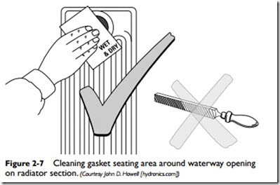
1. Clean the gasket seating areas of the four waterway openings with abrasive cloth (not a file) to ensure that they are free of paint, dirt, and any other contaminants that would interfere with the joining of the two radiator section surfaces (see Figure 2-7).
2. Align the sections accurately. Make sure that the end sections being joined together have opposite threads—in other words, left-handed threads on one section facing right-handed threads on the other.
Note
Sections with an O symbol positioned on the top left-hand side are left-handed threads. Sections with no symbol have right- handed threads.This holds true for all models except 6/58, which is the reverse. The side with a symbol on it has right-handed threads, and the plain side has left-handed threads.
3. Make sure the top and bottom seams on the cast-iron radiator sections match. The top seams are commonly smoother than the bottom ones.
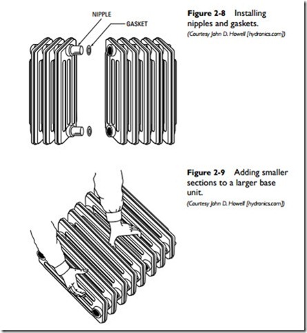
4. Screw the nipples into the first pair of threads by turning only one turn each (see Figure 2-8).
5. Place a jointing gasket over each nipple.
Warning
Do not use jointing compound or PFT tape when jointing gaskets and nipples. Doing so will invalidate the radiator manufacturer’s guarantee.
6. Using the largest radiator section as a base unit, add smaller sections to it by carefully aligning and mating the opposing waterways and protruding nipples (see Figure 2-9).
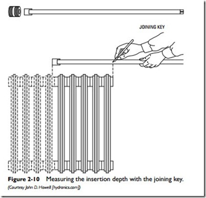
7. Determine the insertion depth of the joining key by measuring it along the top of the radiator from the position of the new joint to the point where it will project from the base unit water- way. Mark this point on the joining key shaft (see Figure 2-10).
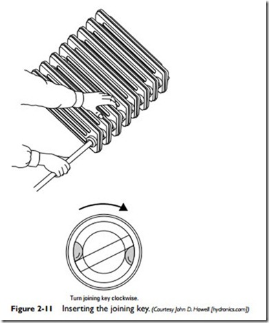
8. Insert the joining key through one of the waterways of the second section (see Figure 2-11). Applying slight pressure, pull the two sections together with one hand and begin to turn the joining key with the other hand until they begin to join together. Stop when both are engaged.
Note
Use a wood block under the joining key to keep it in line. Doing so will ensure that the waterway threads are not damaged by the key shaft.
9. Repeat step 8 by inserting the joining key through the second waterway (each radiator section has a waterway at the top and bottom). Alternate between both waterways a few turns at a time until the end sections meet and the nipples are hand- tight. Do not fully tighten yet.
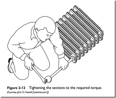
10. Make a final check to ensure that both radiator sections are uniformly aligned, and then fully tighten them to a recommended torque of 140–150 lbs/ft (see Figure 2-12). Do not over-tighten or you may strip the threads.
11. Add additional radiator sections by following the same procedures previously described. When the required number of sections
have been added, lift and carry the completed radiator in the upright position to the installation point. Do not carry it on its side because doing so will place stress on the joints.
Note
Site assembly following the aforementioned procedures should produce a radiator capable of reaching a test pressure of 140 psi.
Remove radiator sections by reversing the aforementioned installation steps. Before attempting to unscrew the nipples with the joining key, look through the waterways for the rough or smooth side of the
nipples. If the rough side is visible, turn the joining key counterclock- wise. If the smooth side is visible, turn it clockwise (see Figure 2-13).
