Installing Electric Baseboard Heaters
Read the manufacturer’s instructions carefully before attempting to install an electric baseboard heater. Particular attention should be paid to wiring instructions and required clearances. Check the local codes and ordinances before beginning any work. All installation must comply with local and national electrical codes, with the former taking precedence.
Caution
To prevent electrical shock and possible equipment damage, always disconnect the power supply before connecting or disconnecting wiring.
Warning
Special care must be taken when installing a line voltage (240 VAC) thermostat.A 240-VAC electric shock may cause serious injury or death.
A minimum clearance is generally required from the bottom of an electric heater to any obstructing surface, such as a floor, floor covering, ledge, or sill. The amount of clearance will depend on the particular unit and manufacturer.
Check the heater operating voltage on the model before installing it. The watt output of an electric heating unit depends on the supply (line) voltage. When the supply voltage equals the rated voltage of the unit, the output will equal the rated watts. Never connect a heater to a supply voltage greater than 5 percent above the marked operating voltage on the model label. A heater connected to a supply voltage that is less than the marked voltage on the model label will result in a watt output that is less than the model label rating. This will cause a reduced heating effect, which should be taken into consideration when determining heating requirements.
Note
Connecting a 120-volt baseboard heater to a 240-volt circuit will cause the heating element to overheat and destroy the heater. Connecting a 240-volt heater to a 120-volt circuit, on the other hand, will result in the heater delivering only about 25 to 30 percent of its designed output.
A change in watt output with respect to a variation in supply voltage may be conveniently calculated with the following formula:
2 X (supply voltage – rated voltage) X amps at related voltage = change in watt output.
For example, the change in watt output for a 120-volt/500- watt/4.2-amp heating unit connected to a 115-volt line can be cal- culated as follows:
2 X (115 volt – 120 volt) X 4.2 amp
= 2 X (-5 volt) X 4.2 amp
= -10 volt X 4.2 amp
= -42 watt change in output.
Thus, the output of this unit at 115 volts will be 458 watts (500 watts – 42 watts). The use of these calculations should be restricted to a +10-volt difference in the supply voltage at 120 volts and a
+20-volt difference, or 208 volts, 240 volts, and 277 volts.
Some manufacturers of electric baseboard heating equipment produce heaters designed for installation as individual units or as components of a larger baseboard heating system. The procedure for installing individual units is as follows:
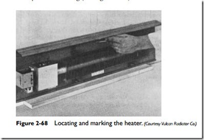
1. Locate the unit on the wall so that the minimum clearance is maintained between the bottom edge of the heater and the finished flooring (see Figure 2-68).
2. Position the unit so that the knockouts in the junction box are aligned with the electrical rough-in location.
3. Locate the wall studs or mullions, and mark the location on the backing of the unit.
4. Drill or punch mounting holes in the backing a suitable dis- tance below the hood and above the bottom edge.
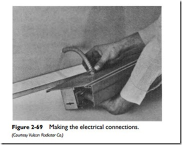
5. Connect armored or nonmetallic sheathed cable through the knockout in the backing or bottom of the junction box (see Figure 2-69). When entering through the backing, make up electrical connector, slide excess cable back into the wall space, and nail or screw the heater backing to the wall.
6. Make electrical connection of branch circuit wiring to the heater. Maintain continuity of grounding (see next paragraph).
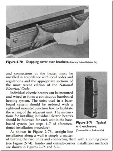
7. Snap the heater cover over the brackets and at the same time align the thermostat operating shaft (built-in thermostats with the hole in the cover) (see Figure 2-70).
8. Slide the end enclosures over each end of the unit (see Figure 2-71), and tighten the cover screws (see Figure 2-72).
For each electric heater unit, continuity of grounding must be maintained through circuit wiring devices. All branch circuit wiring
of butting the two units and connecting them with a joining piece (see Figure 2-74). Inside- and outside-corner installation methods are shown in Figures 2-75 and 2-76.


