Planning a Forced-Warm-Air Heating System
ASHRAE publications (such as recent editions of the ASHRAE Guide) summarize design procedures for planning several types of forced-warm-air heating systems. The following six elements are common to each planning procedure:
1. Calculate the heat loss for each room or space, and from this data determine the total heat loss for the structure.
2. Determine the required furnace-bonnet capacity from the total heat loss of the structure.
3. Determine the location of the diffusers (warm-air outlets) on the building plan.
4. Calculate the required Btu/h delivery of each diffuser.
5. Locate the position of the feeder ducts on the building plan.
6. Calculate the size of each feeder duct on the basis of the total Btu/h delivery it must supply.
Other elements in the design of a forced-warm-air heating sys- tem will be specifically oriented to the characteristics of each system. For example, it is recommended that the maximum length of an extended plenum (nonexistent in a forced-warm-air perimeter system) not exceed 35 ft. The locations and types of warm-air out- lets and return-air inlets selected for the system will also depend upon the type of forced-warm-air heating system used in the structure.
Useful and authoritative sources of information for installing warm-air heating systems are provided by the Air-Conditioning Contractors of America (ACCA) and the National Fire Protection Association (NFPA).
Proprietary systems should always be installed according to the manufacturer’s instructions. Any variation from these instructions increases the probability of error and future problems in the system. It may also void the equipment warranty.
Note
Local codes and ordinances always take precedence over installation instructions provided by manufacturers. When there is a conflict, consult the local regulatory body for a resolution.
Perimeter-Loop Warm-Air Heating Systems
The perimeter-loop warm-air heating system (Figure 6-1) was originally designed for use in residences built on a concrete slab rather than over a basement. The proven success of this duct arrangement in providing efficient and economical heating has resulted in its installation in all types of construction. This is rapidly becoming one of the most popular forms of warm-air heating.
In the perimeter-loop system, round ducts are embedded in the concrete slab or suspended beneath the floor. The air is heated in a warm-air furnace equipped with a blower and is forced through the ducts leading from the furnace to a continuous duct extending around the outer perimeter of the structure. The registers (diffusers) through which the heated air enters the various rooms and spaces
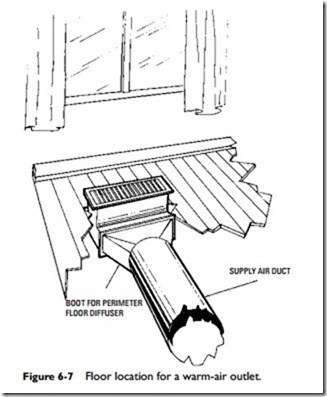
are located along this outer perimeter duct. The most efficient operation can be achieved by placing these warm-air outlets on the floor next to the wall and beneath a window (Figure 6-7). By placing the warm-air outlets here, window drafts are eliminated and the colder outside walls are kept warmed. Research shows that up to 80 percent of the heat loss from a structure can occur at these locations.
The Air Conditioning Contractors of America’s publication Manual 4—Installing Techniques for Perimeter Heating and Cooling is the most authoritative and useful source of information about this subject. (Ask for the most recent edition, because the manual has undergone a number of revisions.)
