1. When the state of a system changes from state 1 to state 3 along the path 1-2-3 as shown in figure, 80 kJ of heat flows into the system and the system does 30 kJ of work. (a) How much heat flows into the system along the path 1-4-3 if work done by the system is 10 kJ (b) when the state of the system is returned from state 3 to state 1 along the curved path, the work done on the system is 20 kJ. Does the system absorb or liberate? (c) If U1 = 0 and U4 = 40 kJ, find the heat absorbed in the process 1-4 and 4-3 respectively.
2. In a certain steam plant the turbine develops 1000 kW. The heat supplied to the steam in the boiler is 2800 kJ/kg, the heat rejected by the system from cooling water in the condenser is 2100 kJ/kg and the feed pump work required to pump the condensate back into the boiler is 5 kW. Calculate the steam flow round the cycle in kg/s.
Solution: WT = 1000 kW
3. An air compressor takes in air at 105 Pa and 270C having volume of 1.5 m3/kg and compressor it to 4.5 x 10⁵ Pa. Find the work done, heat transfer and change in internal energy if the composition is isothermal.
4. A cylinder fitted with piston contains 0.2 kg of N2 at 100 kPa and 300C. The piston is moved compressing N2 until the pressure becomes 1 MPa and temperature becomes 1500C. The work done during the process is 20 kJ. Determine the heat transferred from N2 to the surroundings. Take Cv = 0.75 kJ/kg-K for N2.
5. A closed system consisting of 1 kg of gaseous Co2 undergoes a rev. process at constant pressure causing a decrease of 30 kJ in internal energy. Determine the work during the process. Take Cp = 840 J/kg -0C and Cv = 600 J/kg –0C
6. The specific heat at constant pressure of one kg fluid undergoing a non-flow constant
pressure process is given by ![]() . Where T is in 0C. The pressure during the process is maintained at 2 bar and volume changes from 1m3 to 1.8m3 and temperature changes from 500C to 4500C. Determine (i) Heat added (ii) Work done (iii) Change in i.e., (iv) Change in enthalpy.
. Where T is in 0C. The pressure during the process is maintained at 2 bar and volume changes from 1m3 to 1.8m3 and temperature changes from 500C to 4500C. Determine (i) Heat added (ii) Work done (iii) Change in i.e., (iv) Change in enthalpy.
7. Air at 1.02 bar, 220C, initially occupying a cylinder volume of 0.015 m3, is compressed reversibly and adiabatically by a piston to a pressure of 6.8 bar. Calculate i) the final temperature, ii) the final volume, iii) The work done on the mass of air in the cylinder.
i.e., work done on the system = 2.74 kJ
8. A storage battery, having a terminal potential of 12 volts draws a current of 8 amps for 2.5 hrs. If the stored energy of the battery decrease by 1250 kJ, evaluate the heat interaction across the boundary enveloping the storage battery.
9. A 0.75 kW motor drives a paddle wheel which stirs for an hour 50 kg of water contained in a thermally insulated rigid tank. Assuming the process to be a constant volume, determine rise in temperature and change in internal energy of water. Take C for water = 4.186 kJ/kg –0K
10. A work piece of 30 cm dia is being turned on a lathe and the tangential force on the cutting tool is estimated to be 100 N. When the turning operation is executed for 10 minutes, the increase in the int. energy of the work piece works out to be 125 kJ. Make calculations for the heat transfer from the work piece if the work piece turns at 180 rev./min.
11. A closed rigid vessel containing 10 kg of oxygen at 290 k is supplied heat until its pressure becomes two-fold that of initial value. Identity the process and calculate the final temperature, change in internal energy, enthalpy and heat interaction across the system boundary. Take Cv = 0.65 kJ/kg –0k
First Law of Thermodynamics to open system:
In the case of closed system there is only energy transfer across the system boundary. But in many engineering applications we come across open systems where in both mass and energy transfer takes place. The energies that cross the system boundary are as follows.
1) Internal energy: Each kg of matter has the internal energy ‘u’ and as the matter crosses the system boundary the energy of the system changes by ‘u’ for every kg mass of the matter that crosses the system boundary.
2) Kinetic energy: Since the matter that crosses the system boundary will have some velocity say V each kg of matter carries a k.E. V 2 / 2 thus causing the energy of the system to change by this amount for every kg of matter entering the system boundary.
3) Potential energy: P.E. is measured with reference to some base. Thus ‘Z’ is the elevation of the matter that is crossing the system boundary, then each kg of matter will possess a P.E. of gZ.
4) Flow energy or Flow work: This energy is not directly associated with the matter crossing the system boundary. But it is associated with the fact that there must be some pumping process which is responsible for the movement of the matter across the system boundary. Thus external to the system there must be some force which forces the matter across the system boundary and the energy associated with this is called flow energy.
Flow Work: Consider a flow process in which a fluid of mass dm1 is pushed into the system at section 1 and a mass dm2 is forced out of the system at section 2 as shown in fig.
 In order to force the fluid to flow across the boundary of the system against a pressure p1, work is done on the boundary of the system. The amount of work done is δW = – F1.dl1, Where F1 is the force and dl1 is the infinitesimal displacement, but F1 = p1A1
Similarly, the work done by the system to force the fluid out of the system at section 2 = + p2v2 Hence net flow work = p2V2 – p1V1
For unit mass, the flow work is (p2V2 – p1V1). Flow work is expressed entirely in terms properties of the system. The net flow work depends out on the end state of the fluid and it is a thermodynamics property. Also the fluid contains energies like internal energy, potential energy and due to the motion of the fluid, kinetic energy, in addition to the flow work. When a fluid enters an open system, these properties will be carried into the system. Similarly when the fluid leaves the system, it carries these energies out of the system. Thus in an open system, there is a change in energy of the system.
5. Control Volume: The first and most important step in the analysis of an open system is to imagine a certain region enclosing the system. This region having imaginary boundary is called control volume, which can be defined as follows.
A C.V. is any volume of fixed shape, and of fixed position and orientation relative to the observer. Across the boundaries of the C.V. apart from mass flow, energy transfer in the form of heat and work can take place just as similar to the energy transfer across the boundaries of a system.
Thus the difference between C.V. and system are
i) The system boundary may and usually does change shape, position, orientation relative to the observer. The C.V. does not by definition.
ii) Matter may and usually does flow across the system boundary of the C.V. No such flow takes place across the system boundary by definition.
First law of thermodynamics for an open system (Flow process):
We have 1st law of thermodynamics to a closed system as,
The subscript O refers to the states of the system within the boundary. In the case of open system, energy is transferred into & out of the system not only by heat and work but also by the fluid that enters into and leaves the boundary of the system in the form of internal energy, gravitational potential energy, kinetic energy in addition to the energy in the flow work. Thus, when the first law is applied to an open system, the energy entering into the system must be equal to the energy leaving the system in addition to any accumulation of energy within the system.
Where state (1) is the entering condition and state (2) is the leaving condition of the fluid. This is a general equation of the first law of thermodynamics applied to open system.
Note: The equation is valid to both open and closed system. For closed system, dm1=0 & dm2 =0
Energy Equation for open system: The general form of first law of thermodynamics applied to an open system is called steady-flow energy equation (SFEE) i.e., the rate at which the fluid flows through the C.V. is constant or steady flow. SFEE is developed on the basis of the following assumptions.
i) The mass flow rate through the C.V. is constant, i.e., mass entering the C.V. / unit time = mass leaving the C.V. /unit time. This implies that mass within the C.V. does not change.
ii) The state and energy of a fluid at the entrance and exit do not vary with time, i.e., there is no change in energy within the C.V.
iii) The rates of heat and work transfer into or out of the C.V. do not vary with time.
For a steady flow process, m& = m& 1 = m& 2 & d(E)0 = 0 as Q ¹ f (T) & W ¹ f (T)
SFEE on the basis unit mass:
Displacement work for a flow process (open system):
From SFEE, when changes in kinetic & potential energies are neglected, δq – δW = dh
Or δW = δq – dh — (1)
From the 1st law of thermodynamics, we have δq – δW = du
For a rev. process, δW = Pdv
δq = du + Pdv
Also, from the definition of enthalpy, h = u + pv
Note: With negligible PE & KE, for a non-flow rev. process, the work interaction is equal to where as for a steady-flow rev. process, it is equal to – ò 2 vdp
Application of SFEE:
i) Nozzle and Diffuser: Nozzle is a duct of varying c/s area in which the velocity increases with a corresponding drop in pressure. Since the flow through the nozzle occurs at a very high speed, there is hardly any time for a fluid to gain or loose heat and hence flow of the fluid is assumed to be adiabatic. And also there is no work interaction during the process, i.e., Ws = 0, Q = 0, Z1 = Z2
 i.e., the gain in KE during the process is equal to the decrease in enthalpy of the fluid. Diffuser is a device to increase the pressure of a fluid during flow with a corresponding decrease in KE. Thus its function is reverse to that of a nozzle. As final velocity V2 in a diffuser is very small, it is very often negligible.
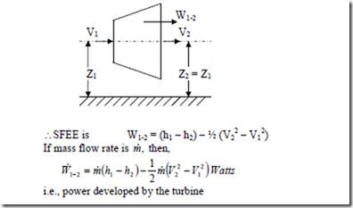
ii) Turbine and Compressor (rotary): Turbine is a device which produces work by expanding a high pressure fluid to a low pressure. The fluid is first accelerated in a set of nozzle and then directed through curved moving blades which are fixed on the rotor shaft. The direction of the fluid changes which it flows through the moving blades, due to which there is a change in momentum and a force exerted on the blades producing torque on the rotor shaft. Since the velocity of flow of the fluid through the turbine is very high,
Compressor is a device in which work is done on the fluid to raise its pressure. A rotary compressor can be regarded as a reversed turbine. Since work is done on the system, the rate of work in the above equation is negative and the enthalpy after compression h2 will be greater than the enthalpy before compression h1.
iii) Throttling Process: When a fluid steadily through a restricted passages like a partially closed valve, orifice, porous plug etc., the pressure of the fluid drops substantially and the process is called throttling. In a throttling process, expansion of the fluid takes place so rapidly that no heat transfer is possible between the system and the surroundings. Hence the process is assumed to occur adiabatically. The work transfer in this process is zero.
In a throttling process, the enthalpy remains constant. The throttling process is irreversible because when a fluid is throttled, it passes through a series of non-equilibrium states.
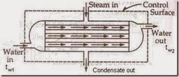
iv) Heat Exchanger: A heat exchanger is a device in which heat is transferred from one fluid to another. It is used to add or reduced heat energy of the fluid flowing through the device. Radiator in an automobile, condenser in a steam power and refrigeration plants, evaporator in a refrigerator are examples of heat exchangers. There will be no work interaction during the flow of the fluid through any heat exchanger.
Eg: i) Steam condenser: Used to condense the steam. It a device in which steam loses heat as it passes over the tubes through which water is flowing.
Figure: Heat Exchanger
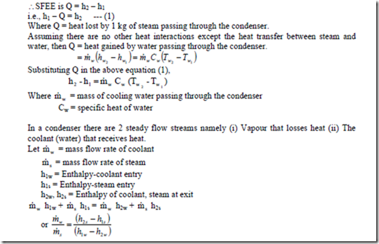
We have DKE = 0, DPE = 0 (as their values are very small compared to enthalpies) W = 0 (since neither any work is developed nor absorbed)
SFEE is Q = h2 – h1 i.e., h1 – Q = h2 — (1)
Where Q = heat lost by 1 kg of steam passing through the condenser.
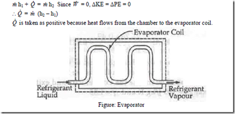
ii) Evaporator: An evaporator is a component of a refrigeration system and is used to extract heat from the chamber which is to be kept at low temperature. The refrigerating liquid enters the evaporator, absorbs latent heat from the chamber at constant pressure and comes out as a vapour. SFEE is
v) Boiler: It is an equipment used for the generation of the steam. Thermal energy released by combustion of fuel is transferred to water which vapourizes and gets converted into steam at the desired pressure and temperature. The steam thus generated is used for
-
Producing mechanical work by expanding it in steam engine or steam turbine.
-
HeaLting the residential and industrial buildings in cold weather and
-
Performing certain processes in the sugar mills, chemical and textile industries.
1. Velocity change is negligible V1 = V2
2. Change in elevation is also negligible Z2 = Z1
3. Work done = 0
Related posts:
Incoming search terms:
- air at 1 02 bar 22
- heat rejected by the system or on the system work done
- s f e e for seam and water turbine
- Air at 1 02 bar 22°C initially occupying a cylinder volume of 0 015m is compressed reversibly and adiabatically by a piston to a pressure of 6 8 bar determine the final temperature the final volume and the work done on the mass of air in the cylinder
- air of pressure 1 02bar at temperature of 22•C
- In a certain steam plant the
- a steam power plant develops 1000KW the heat supplied to the steam in the boiler is 2800KJ/Kg the heat rejected by the system to cooling water in the condenser is 2100KJ/Kg and the feed pump work required to pump the condensate back into the boiler is 5KW
- a closed regid vessel containing 10 kg of oxygen at 290 K is supplied heat untilled ots pressure becomes double
- the rate at which heat is rejected from the turbine
- a battery having terminal potential 6v draws a current of 10a for 5 hours stored energy is decreased by 1000kj determine heat interaction
- calculate the enthalpy of 3 kg of fluid that occupies a volume of 1 5
- In certain steam plant the turbine develop
- in a certain plant turbine develops 1000kw the heat supplied
- mass flow rate of cooling water in condenser in steady flow energy equation
- if the workdone on a closed system is 20kj /kg and 40kj/kg heat is rejected from the system its internal energy decreased by how much
- if the work done on a closed system is 20 kj/kg and 40 kj/kg heat is rejected from the system its internal energy decreased by
- How to find steam flowround cycle
- how to calculate non flow steam required to heat water
- how the thermodynamic processe involved?
- in a certain steam plant operating in a closed cycle the turbine develops 1000 kW The heat supplied to the steam in the boiler is 2800 kJ/kg the heat rejected by the system to the cooling water in the condenser is 2100 kJ/kg and the feed pump work require
- internal energy change in first law of thermodynamics
- In a steam plant the turbine develops 1000kW The heat supplied to the steam in the boiler is 2800kJ/kg the heat rejected by the steam to the cooling water in the condenser is 2100kJ/kg and the feed-pump work required to pump the condensate back into the b
- In a certain steam plat the turbine developedts 1000kw
- In a certain steam plant the turbine develops 100w
- In a certain steam plant the turbine develops 1000kW the heat supplied to the boiler is 2800kJ/Kg the heat rejected by the steam to the cooling water in the condenser is 2100kJ/Kg and the feed pump work required to pump condensate back into the boiler is
- in a certain steam plant the turbine develops 1000 kw
- in one section of water flow the pressure is 1500 kpa if internal energy is 20 kj/kg find the enthalpy at this point
- in a certain steam plant tge turbine develops 1000 KW
- in a certain steam plant operating in a closed cycle the turbine develops 1000kW The heat supplied to the steam in the boiler is 2800kJ/kg the heat rejected by the system to the cooling water in the condenser is 2100kJ/kg and the feed pump work required t
- heat rejected by steam when it take mass of steam
- find specific enthalpy of cooling water in steam condenser
- a turbine in a certain steam plant develops 1100kw worth of power the heat supplied to the steamin the boiler
- a steam power plant develops 1000kw the heat supplied to the steam in the boiler is 2800 kj/kg the heat rejected by the system to cooling water in the condenser is 2100kj/kg and the feed pump work required to pump the condensate back into the boiler is 5k
- a steam power plant develops 1000 kw
- A steam power plant devekop 1000 kw the heat supplied to the steam in the Boiler is 2800kj/kg
- a cylinder contains 20 kg of n2
- A closed system executes adiabatic process due to which a change in internal energy takes place; A work of 10KJ is done by the system on surroundings during this process Determine the change of specific internal energy of system if system contains mass of
- A certain Steam plant th
- work of pump in potential and kinetic energy problems with solutions in thermodynamics
- air at 1 02 bar
- air at 1 02 bar 22 degrees initially occupying a cylinder volume of 0 015 is compressed reversibly and adiabatically by a piston to a pressure of 6 8 bar calculate final temperature final volume and work done
- air at 1 02 bar 22C initially occupying a cylinder volume of 0 015
- equation for change in internal energy with pressure change
- devices that use s f e e thermodynamic
- calculate the enthalpy of 3 kg of fluid that occupies a volume of 1 5 m^3 if a internal energy is 3 5Mjoules/kg and pressure 0 3MN/m^2?
- a certain steam power plant thermally develops 1500kw the heat supply to the steam in the boiler is 2800kj/kg
- calculate the amount of heat rejected by the steam
- at a pressure 10 bar and enthalpy 2000kj/kg
- air of pressure 1 02 bar at a temperature of 22 C initially occupying a cylinder of volume of is reversibly and adiabatically compressed
- air at 1 02 bar with temperature 22C intially occupying a cylinder volume 0 015


