Transformers
A transformer is an inductive stationary device designed to transfer electrical energy from one circuit to another. Each transformer contains a primary and secondary winding. A changing voltage applied to one of the windings induces a current to flow in the other winding. In this manner, electrical energy is transferred from one circuit to another. Usually the changing voltage is applied to the primary winding and a current is induced in the secondary. The electrical energy may be transferred at the same voltage (a coupling trans- former), at a higher voltage (a step-up transformer), or at a lower voltage (a step-down transformer).
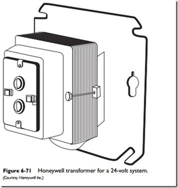
The transformers used in heating and cooling systems are step- down transformers. They are designed to reduce (step down) the higher line voltage power to the 24 to 30 volts required by low- voltage control circuits. Some models are designed to power thermostats, gas valves, and relays in HVAC 24-volt systems. Others are designed primarily for powering air-conditioning systems, although they can be used in other applications if they do not exceed the listed ratings. In most installations, the room thermostat is operated by a low-voltage (24-volt AC) circuit. Some gas valves are also operated by a low-voltage circuit.
All wiring connections to transformers must be done in accordance with the recommendations of the National Electrical Code. A single thin copper wire is used in a low-voltage circuit. It is commonly (but not always) identified by its red and black insulation. High-voltage circuits use a larger-diameter wire that is commonly covered with white or black insulation.
Note
If you have any doubts about the voltage of the circuit, check it with a voltmeter before beginning any work. Keep in mind that a small number of transformer models are connected to high-voltage circuits, not the customary low-voltage ones.
Interconnected transformer secondaries are not permitted by the National Electrical Code. One method of avoiding the need for interconnecting transformers is by using a single transformer rated to carry both the heating and cooling load. Using a thermostat and subbase combination with isolated heating and cooling circuits is also an acceptable method. Still another successful method utilizes an isolating relay to isolate the heating power supply from the cool- ing power supply.
Sizing Transformers
Transformers are not 100 percent efficient. There will generally be some loss of energy between the primary and secondary coils. In any event, the secondary coil must have enough remaining energy to drive the load connected to it.
When the equipment in a heating and/or cooling system is not adequately powered, check the transformer primary and secondary voltages. If these readings are within plus or minus 10 percent of the rated voltage and there is no problem with the wiring, the trans- former may not be large enough for the system. A transformer too small for the system can be a very serious matter because it will sup- ply abnormally low voltage to the control circuit. As a result, con- tactors or motor starters will not operate properly, and eventually the compressor may suffer damage.
When replacing a transformer, always select one that is the same size or larger than the one being replaced. For new installations, follow the equipment manufacturer’s recommendations.
The capabilities of a transformer are described by its electrical rating. This information will include the primary voltage and frequency, the open-circuit secondary voltage, and the load rating in volt-amperes (VA).
The Class 2 transformers used in low-voltage control circuits have a maximum load rating of 100 VA and a maximum open- circuit secondary voltage of 30 volts. The secondary current must also be limited. This can be accomplished by using an energy-limiting transformer or by adding a 3.2-ampere (or less) fuse in the secondary. In the latter case, the maximum load rating of a typical 4-volt Class 2 transformer is 77 VA (24 volts X 3.2 amperes = 77 VA).
Installing Transformers
Always closely follow the transformer manufacturer’s installation instructions, because they will vary depending on the model and the specific application. The following guidelines apply to most trans- formers:
Caution
Never attempt to remove or install a transformer unless you are a qualified electrician or have the required training and experience. Improper removal or installation can result in damaged equipment and/or serious electric shock.
Note
The following guidelines cannot replace the specific step-by-step instructions in the transformer manufacturer’s installation instructions.
1. Disconnect the power supply to prevent equipment damage or electric shock before attempting to remove or install a transformer.
2. Separate and tape each exposed, unused lead wire. Note: All wiring must comply with local electrical codes and ordinances.
3. Do NOT short the transformer secondary terminals or you may burn out the overload protection.
4. Check the specification section of the transformer for lead wire color-coding (see Figure 6-71).
5. Connect the primary lead wires to the line voltage power supply.
6. Connect the transformer secondary to the 24-VAC control system. If the transformer model has a primary or secondary conduit spud, connect the wires first and then screw the con- duit onto the spud.
7. Check the secondary voltage before connecting the trans- former to the power supply.
8. Turn on the power supply and operate the system for one or two complete cycles.
