Sequence Controllers
A sequence controller (also referred to as a sequencer or step controller) is a device used to operate two or more electric switches in
predetermined sequence. This function is accomplished by means of a proportional electric or pneumatic operator.
Sequence controllers are most commonly used to provide sequenced starting of a number of electric heating elements or compressor motors. This prevents the massive drawing on the current that simultaneous starting would cause.
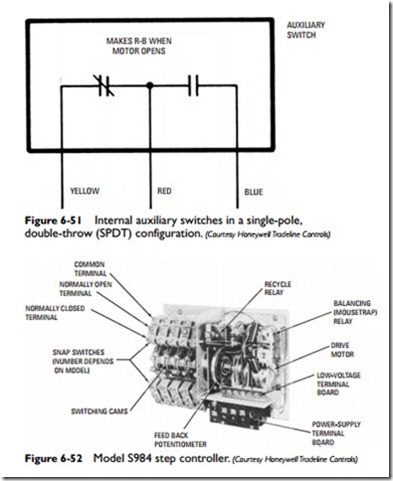
Sequence controllers are manufactured in a number of different sizes and capacities. The Honeywell S984 step controller, shown in Figure 6-52, provides up to 10 adjustable switches. It can also be used to control at least two other step controllers when greater switching capacity is required.
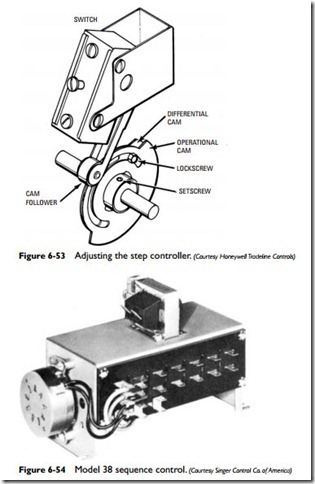
Each switch in the Honeywell step controller is operated by a cam mounted on the main shaft (see Figure 6-53). Adjustments of the step controller can be made by setting each of the switches to make or break a circuit at the correct time or angle in the stroke. The procedure for setting the switches in the Honeywell step con- troller is as follows:
1. Loosen the setscrew so that the cam assembly will turn freely on the motor shaft.
2. Run the step controller motor until the desired switch make point is reached. This will be determined by the time or degrees of camshaft rotation.
3. Turn the cam until the switch just makes and tighten the setscrew.
4. Run the step controller back to the desired switch break point.
5. Loosen the lockscrew and turn the differential cam so that the switch will break at this point.
The instructions for adjusting the Honeywell step controller recommended setting the make points of all the switches first and then setting all the break points. This procedure avoids unnecessary cycling of stages.
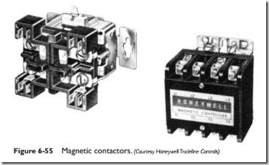
The sequence controller, shown in Figure 6-54, provides time- delay switching of up to eight electric heater banks and a fan or pump. When the thermostat calls for heat, it starts the low-voltage
sequence motor, which operates the rotating cams. The first cam locks in the motor circuit so that if the thermostat should break immediately, the motor will continue running, rotating all cams back into the starting position.
The second cam starts the fan. The remaining cams switch on the heater banks with a specific time delay between the energizing of each bank. The motor will stop running after 180ºrotation as long as the thermostat calls for heat. The fan and all heater banks will
continue to be energized. When the thermostat is satisfied, the motor starts again and switches off the heater banks at the predetermined time interval. The fan is deenergized, and the motor stops when the cams are back in the starting position.
Contactors
A contactor is essentially a switching relay device that functions as a primary control in a cooling system. Its operation is based on either magnetic or mercury-to-mercury contact action.
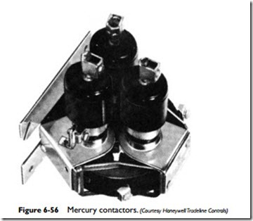
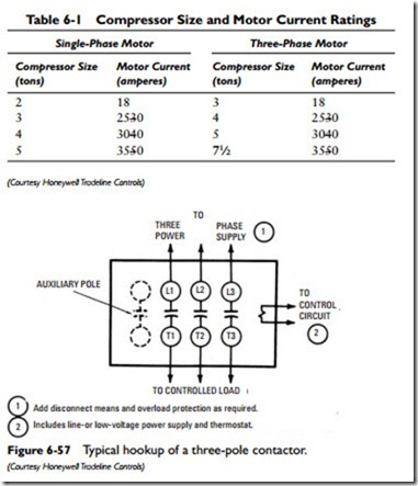
A magnetic contactor (see Figure 6-55) is similar in design and operating principle to a relay but is larger in size. In a mercury contactor (see Figure 6-56), the contacts are made and broken between two pools of mercury separated by a ceramic insulator. Mercury-to- mercury contact action results in a quieter operation than magnetic contactors can provide, but a mercury contactor has the disadvan- tage of being position sensitive. It must be mounted in an upright position.
A contactor is used for applications requiring heavy current, high voltage, or a large number of poles—in other words, applications where the capacity of a relay would be inadequate.
In a cooling system, an electric-driven compressor motor may be cycled by a thermostat (either a low-voltage or line voltage type) or a low-pressure control. Because these controllers are usually unable to handle the high current drawn by the compressor motor,
a contactor is installed between the thermostat or pressure control and the motor where it functions as a primary control. This contactor is the electrical contact switch to which the main electric power is supplied. When activated by the room thermostat, the contactor causes the compressor and condenser blower motor in an air- conditioning system to begin operating. Contactors are used to control all but the smallest compressor motors.
The size of the contactor selected for use in a cooling system will depend on such variables as the size and type of compressor motor and the auxiliary loads.
Both single-phase and three-phase motors are used in compres- sors. As shown in Table 6-1, the motor current (expressed in amperes) will vary according to the size of the compressor. Contactors are rated in amperes and should be selected to match the rating of the compressor motor. The number of pole contacts is also an important consideration in selecting a contactor. A one- or two-pole contactor is required for a single-phase compressor motor, and a three-pole contactor for a three-phase motor. Auxiliary poles may be used for interlock switching, fan loads, or crankcase heaters (see Figure 6-57).
Troubleshooting Contactors
Always check the fuse box (or circuit breakers) first to make certain that the fuses are good and the switch is in the on position. If this is not the source of the problem, then set the thermostat and base to cooling position and check for continuity across contacts. If the circuit is open, repair or replace the thermostat.
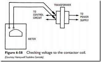
If the system fails to start and the contactor is open and buzzing, check the voltage at the contactor coil (see Figure 6-58). Normal voltage will be within plus or minus 10 percent of the rated coil volt- age. Subnormal voltage may be caused by an undersized transformer or low voltage at the supply side of the transformer. Thermostat wiring that is too long can also cause a subnormal voltage reading. A normal voltage reading under these circumstances (that is, an open, buzzing contactor) is generally caused by a tight or fouled contactor armature. The armature should be cleaned or the contactor replaced.
If the system compressor will not start and the contactor is open but not buzzing, the contactor coil may not be powered. A voltage and continuity check must be run to locate the problem. This is a more complicated procedure than the one described for an open, buzzing contactor.
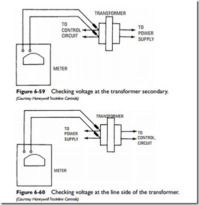
The voltage to the contactor coil should be checked first (see Figure 6-58). If the voltage is normal (within plus or minus 10 percent of the rated voltage), the contactor should be replaced. If a zero voltage reading is obtained, check the voltage at the transformer secondary (see Figure 6-59). If a zero voltage reading is obtained, check the line voltage side of the transformer (see Figure 6-60). A normal supply voltage reading here indicates that the transformer is defective and should be replaced. A zero voltage reading, on the other hand, indicates a problem with the power supply. Check the fuses, circuit break- ers, line disconnect switch, and the power at the service entrance.
If the voltage checked at the transformer secondary (as shown in Figure 6-59) is normal, the control circuit to the contactor coil is open. With a continuity checker, jump across the terminals of the following controls:
• Low-pressure switch
• High-pressure switch
• Room thermostat
• Heating/cooling interlock switch
• Time-delay switch
• Lockout relay
If the system starts with a particular control out of the circuit, the control is probably defective and needs to be replaced. If none of these controls is defective, check the circuits for broken wires or loose connections. An open internal thermostat or overload relay switch in the compressor is another possible cause.
If the compressor hums but will not start, and the contactor remains closed, the problem may be in the motor starting circuit.
Check the motor circuit wiring for loose or broken wires. If there is no problem with the wiring, check the starting capacitors and motor starter. A defective motor is also a possibility. If the motor starting circuit is not defective, check for abnormal system pressures. Another possible cause is a tight, stuck, or burned-out compressor.
If the contactor is closed and the compressor motor neither starts nor hums, check the continuity of the overload switch and the open compressor motor windings. Check also for broken or loose wiring. If none of these is the cause, the contacts in the contactor are probably burned. Replace the contacts.
