Construction Details
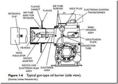
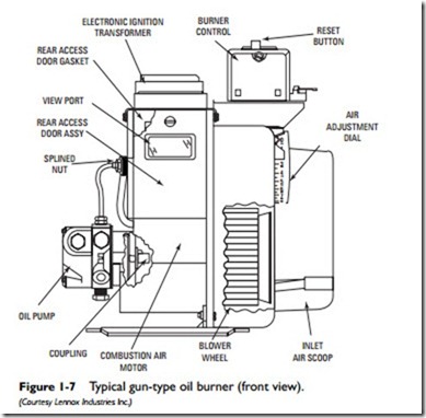
The principal components and parts of a gun-type, high-pressure atomizing oil burner used in residential and light commercial oil heating systems are illustrated in Figures 1-6 and 1-7. The
construction details of gun-type oil burners will vary somewhat in different makes and models, but the overall design of these burners is now nearly standardized. The components and parts of a typical gun-type oil burner can be divided into the following categories:
1. Burner control.
2. Primary safety control.
3. Gun assembly.
4. Ignition transformer.
5. Burner motor and coupling.
6. Fuel pump.
7. Combustion air blower.
Burner Control
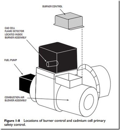
The burner control is the operational control center of the burner.
As shown in Figures 1-6 and 1-7, it is located on the right side of the burner assembly directly above the combustion air blower housing. It operates in conjunction with the primary control and a bimetallic
temperature sensor. When the room thermostat calls for heat and the ignition cycle begins, the burner control will start the burner only when the cad cell detects (proves) a flame. The burner control shuts off the burner if the cad cell fails to prove the flame or if the bimetallic sensor detects a temperature too high for safe operation.
Primary Safety Control
The primary safety control is an automatic safety device designed to stop the flow of fuel oil at the burner should ignition or flame failure occur. Modern oil-fired furnaces and boilers use a cad cell as the primary control to prove the flame; older ones were equipped with a stack detector primary control. The former is mounted inside the burner behind the access door (see Figure 1-8), and the latter is located in the stack.
Gun Assembly
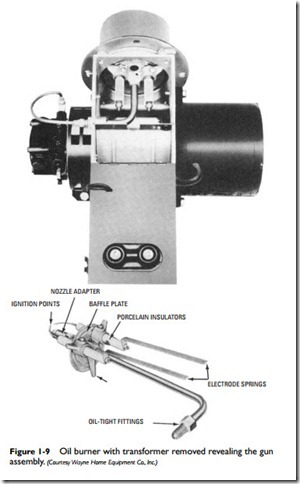
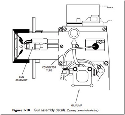
The oil burner gun assembly consists of a burner nozzle, the electrodes, and a tube connecting the electrodes to the fuel pump (see Figure 1-9). The burner nozzle changes the fuel oil into a form that can be burned in the combustion chamber. It accomplishes this by forcing the oil under pressure through a small hole at the end of the nozzle. The atomized fuel oil is ignited by spark from the electrodes.
Ignition Transformer
A step-up ignition transformer located on top of the burner assembly produces the voltage used by the electrodes to ignite the fuel oil. This type of transformer is designed to increase the voltage of a high-voltage (110 VAC) circuit to the ultrahigh 14,000 volts required to ignite the fuel oil.
Burner Motor and Coupling
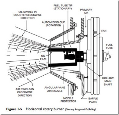
As shown in Figure 1-5, the burner motor is located on the right side of the oil burner assembly. The drive shaft of the burner motor is connected to both the fuel pump and the combustion air blower by a coupling that functions as the drive shaft for both of these units. A burner motor is also sometimes called an oil pump motor or a pump motor because it is connected to and drives the fuel (oil) pump.
Fuel Pump
The fuel pump (also called an oil pump or a fuel unit) is used to draw fuel oil from the storage tank and deliver it under high pres- sure (100 to 140 psi) to the nozzle assembly (see Figure 1-11). It is driven by the burner motor and coupling and is located on the left side of the oil burner.
Combustion Air Blower
The combustion air blower is also driven by the burner motor and coupling. It is located between the burner motor and the fuel pump. Its function is to introduce the required amount of air for the
combustion process. The amount of air can be manually adjusted by an air adjustment gauge located between the blower wheel and the inlet air scoop (see Figure 1-7). Depending on the oil burner manufacturer, a combustion air blower is also sometimes called a blower wheel, a burner motor fan, or an induction blower. Do not confuse the combustion air blower with the furnace indoor blower. The former delivers air to the oil burner for combustion. The latter delivers the heated air to the rooms and spaces inside the structure.
