TESTING THE STATOR WINDING
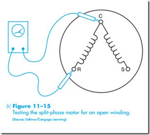
The stator winding of a single-phase motor is generally tested with an ohmmeter. The ohmmeter test can be used to determine if a winding is open or grounded. Many single-phase motors have one lead of the run and start windings connected as shown in Figure 11–15. To test the windings for an open, connect one ohmmeter lead to the common motor terminal, and the other meter lead to the run winding. The ohmmeter should indicate continuity through the winding. The resistance of the run winding of a single-phase motor can vary greatly from one motor to another. The winding resistance of a single-speed motor may be only one or two ohms, while the resistance of a multi-speed fan motor may be 10 to 15 ohms.
To test the start winding for an open, connect the ohmmeter leads to the common terminal and the S terminal. The start winding should indicate continuity, and should have a higher resistance than the run winding. This difference of resistance may not be great, but the start winding should have a higher resistance than the run winding.
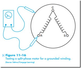
To test the stator winding for a ground, connect one of the ohmmeter leads to the case of the motor, Figure 11–16. Alternately check each motor terminal with the other ohmmeter lead. The ohmmeter should indicate no continuity between either winding and the case of the motor.
A shorted start winding can sometimes be detected by the fact that the motor will not start, but will run if the shaft is turned by hand. The motor will produce a humming sound but will not turn when power is first applied to it. The shaft can be turned in either direction by hand and the motor will continue to run in that direction.
REVERSING DIRECTION OF ROTATION
The direction of rotation of a split-phase motor can be reversed by changing the start winding leads or the run winding leads, but not both. The rotation is generally reversed by changing the start winding leads with respect to the run winding. Some motor manufacturers bring both start winding leads to the outside of the motor. This permits the service technician to decide the direction of rotation the motor is to turn when it is installed on the unit.
DUAL-VOLTAGE MOTORS
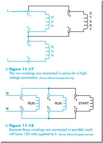
Single-phase motors can also be constructed to operate on two separate voltages. These motors are designed to be connected to 120 or 240 volts. A common connection for this type of motor contains two run windings and one start winding, Figure 11–17. The run windings are labeled T1–T2, and T3–T4. The start winding is labeled T5 and T6. In the circuit shown in Figure 11–17, the windings has been connected in parallel with one of the run windings. This causes the start winding to have an
applied voltage of 120 volts also. Notice that each of the windings has 120 volts connected to it, which is the rating of the windings.
If the motor is to be operated on a 120 volt line, the windings are connected in parallel as shown in Figure 11–18. Because these windings are con- nected in parallel, each will have 120 volts applied to it.
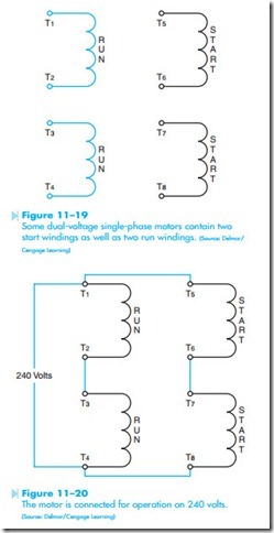
Some dual-voltage motors will contain two start windings as well as two run windings, as shown in Figure 11–19. The run windings are labeled T1 through T4, the same as dual-voltage motors that contain only one start winding. One of the start windings is labeled T5 and T6. The second start winding is labeled T7 and T8. If the motor is to be connected for operation on 240 volts, the run windings are connected in series by connecting T2 and T3 together, and the start windings are connected in series by connecting T6 and T7 together. The start windings are then connected in parallel with the run windings, as shown in Figure 11–20. The direction of rotation can be changed by reversing T5 and T8.
If the motor is operated on 120 volts, the run and start windings are connected in parallel as shown in Figure 11–21. If the motor is to be reversed, leads T5 and T7 are changed with leads T6 and T8. Some
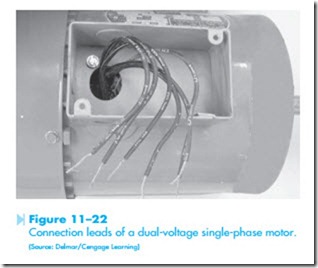
manufacturers label the start winding leads T5 and T8 even if they contain only one start winding. The connection leads of a dual-voltage single-phase motor are shown in Figure 11–22.
