RESISTANCE-START INDUCTION- RUN AND CAPACITOR-START INDUCTION-RUN MOTORS
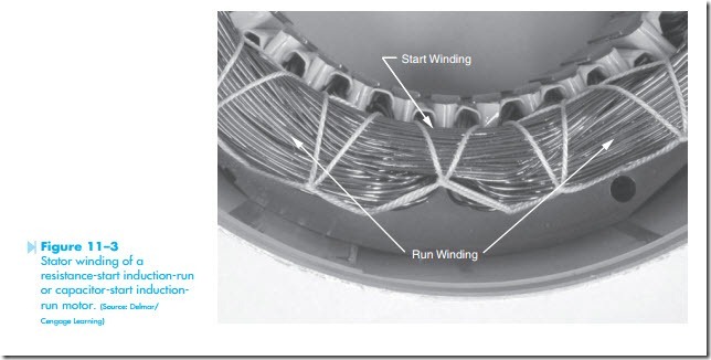
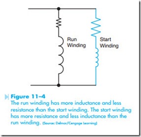
Resistance-start induction-run and capacitor-start induction-run motors are very similar in construction. The stator winding of both motors contains both a start winding and a run winding. The start winding is made of smaller wire and placed higher in the metal core material than the run winding, as shown in Figure 11–3. Since the start winding is made with smaller wire than the run winding, it will exhibit a higher resistance than the run winding. Placing the run winding deeper in the metal core material causes it to exhibit a greater amount of inductance that the start winding. Electrically, the winding appears similar to the circuit shown in Figure 11–4. The stator is constructed in this
manner to produce a phase shift between the cur- rent flowing through the run winding and the current flowing through the start winding. Both the resistance-start and capacitor-start induction- run motors start rotation by producing a rotating magnetic field in the stator winding. Recall that a rotating magnetic field cannot be produced with a single phase.
Resistance-Start Induction-Run Motor
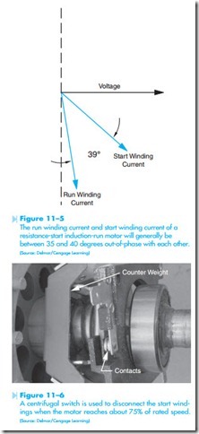
The rotating magnetic field of the resistance-start induction-run motor is produced by the out-of-phase currents in the run and start windings. Since the run winding appears more inductive and less resistive than the start winding, the current flow in the run winding will be close to 90 degrees out-of-phase with the applied voltage. The start winding appears more resistive and less inductive than the run winding, causing the start winding’s current to be less out-of-phase with the applied voltage, as shown in Figure 11–5. The phase-angle difference between current in the run winding and current in the start winding of a resistance-start induction-run motor is generally 35 to 40 degrees. This is enough phase- angle difference to produce a weak rotating field, and consequently a weak torque, to start the motor. Once the motor reaches about 75% of its rated speed, the start winding is disconnected from the circuit and the motor continues to operate on the run winding. In nonhermetically sealed motors, the start winding is generally disconnected with a centrifugal switch. A centrifugal switch is shown in Figure 11–6. The contacts of the centrifugal switch are connected in series with the start winding, as
shown in Figure 11–7. When the motor is at rest or not running, the contacts of the centrifugal switch are closed and provide a circuit to the start winding. When the motor is started and reaches about 75% of its rated speed, a counterweight on the centrifugal switch moves outward because of centrifugal force, causing the contacts to open and disconnect the start winding from power. The motor continues to operate on the run winding.
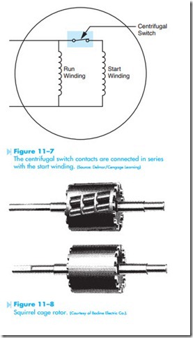
When the start winding is disconnected from the circuit, a rotating magnetic field is no longer produced in the stator. This type of motor continues to operate because of current inducted in the squirrel cage windings in the rotor. Squirrel cage rotors are so named because they contain bars inside the rotor that would resemble a squirrel cage if the laminations were removed, as shown in Figure 11–8.
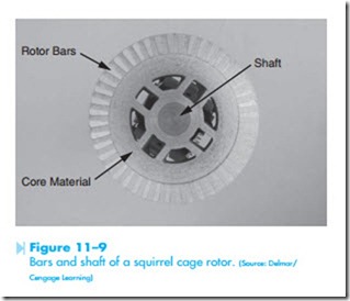
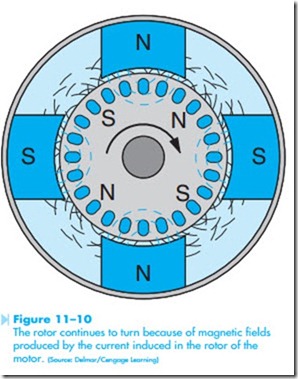
A squirrel cage is a device that is often placed inside the cage of small pets such as hamsters to permit them to exercise by running inside the squirrel cage. A squirrel cage rotor that has been cut in half clearly shows the bars and motor shaft, as shown in Figure 11–9. The bars of the turning squirrel cage rotor winding cut through lines of magnetic flux, causing an induced voltage in the rotor. Since the rotor bars are shorted together at each end, current flow through the rotor bars produces a magnetic field in the rotor. Alternate magnetic fields are produced in the rotor, causing the motor to con- tinue operating, as shown in Figure 11–10. This is the same principle that permits a three-phase motor to continue operating if one phase is lost and the motor is connected to single-phase power. The main difference is that the split-phase motor is designed to operate in this condition and the three- phase motor is not. Resistance-start and capacitor- start induction-run motors are rugged and will provide years of service with little maintenance. Their operating characteristics, however, are not as desirable as those of other types of single-phase motors. Due to the way they operate, they have a low power factor. They will draw almost as much current when the motor is running at no load as they will when the motor is running at full load. Typically, if the motor has a full-load current draw of 8 amperes, the no-load current may be 6.5 to 7 amperes.
Capacitor-Start Induction-Run Motors
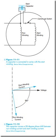
Capacitor-start induction-run motors are very similar to resistance-start induction-run motors. The design of the stator winding is basically the same. The main difference is that a capacitor is connected in series with the start winding, as shown in Figure 11–11. Inductive loads cause the current to lag the applied voltage. Capacitors, however, cause the current to lead the applied voltage. If the starting capacitor is sized correctly, the start winding current will lead the applied voltage by an amount that will result in a 90-degree phase shift between the run winding current and the start winding current, producing an increase in the amount of starting torque, as shown in Figure 11–12. If the capacitance of the start capacitor is too great, it will cause the start winding current to shift more than 90 degrees out-of-phase with the run winding current and starting torque will be reduced. When replacing the start capacitor for this type
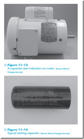
of motor, the micro-farad rating recommended by the manufacturer should be followed. It is permissible to use a capacitor with a higher voltage rating, but never install a capacitor with a lower voltage rating. A capacitor-start induction-run motor is shown in Figure 11–13. A typical starting capacitor is shown in Figure 11–14.
Related posts:
Incoming search terms:
- starting winding and running winding resistance
- Resistance start induction run motor
- resistance start induction run
- resistance start induction motor
- resistance of starting and running winding
- the application of resistant start induction run motor is
- capacitor start induction run motor
- rsir motor
- rsir circuit
- induction start induction run
- starting and running winding resistance
- motor wimding
- difference between starting winding and running winding
- what does changing csa of start and run windings do
- starting winding resistance
- capacitor start torque and speed calculations
- on a single phase motor which is the run coil
- how to tell if a motor is split phase or cap start induction run
- main start run windings of sub
- run and start winding restance
- resistance between run and start windings
- single phase motor starting and running winding resistance
- how to find the compressors run & main winding
- difference between starting and running winding resistance
- resistance start
- induction start induction run motor
- resistance start induction run motor applications
- resistance start capacitance
- resistance between start and run winding
- difference between start and run motors
- how many much registance starting winding or running
- start winding and run winding resistance
- resistance start capacitor run motor
- starting winding and running winding resistance difference
- Partical Resistance start Induction Run RSIR
- Application of resistant start induction run motor
- start winding resistance
- resistance of start windings and run windings
- resistance start induction motor theory
- application of resistance start induction run motor
- how to know difference between starting and running winding
- run and start winding
- Resistance between running and starting winding of motor
- difference between number of turns starting and running winding
- single phase motor starter and main coil resistance
- Resistance of 1 phase motor starting and running coil
- resistance start induction run motor mcq ans
- in fan winding which winding has more resistance
- Run winding definition
- resistance start motor
