Gas Piping and Piping Connections
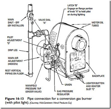
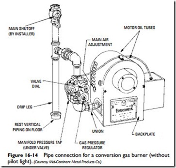
Figures 16-13 and 16-14 illustrate the piping connections necessary for two different models of gas-fired conversion burners.
Note:
All local codes and ordinances take precedence over the instructions in the burner manufacturer’s installation manual. If there is no manual available, the installation of the burner must conform to the manufacturer’s instructions, the regulations of the National Fire Protection Association, and the pro- visions in the latest editions of the National Electrical Code (ANSI/NFPA70) and the National Gas Code (ANSI Z223.1).
No matter what type of gas-fired conversion burner you decide to use, it must be allowed to develop its rated capacity. This can be accomplished by making certain the burner is connected to a gas supply containing sufficient pressure.
In addition to providing for a gas supply with sufficient pressure, the following recommendations are also offered:
1. Provide for a separate gas-supply line of 1-in pipe size direct from the meter to the burner (ample for runs up to 60 ft long).
2. Install an intermediate regulator if the line pressure exceeds 13.5-in W.C (water column).
3. Connect the burner to the piping as shown in Figures 16-13 and 16-14.
4. Install a manually operated main shutoff valve 4 to 5 ft above the floor on the vertical pipe.
5. Make certain the pipe is clean and free of any scale.
6. Use malleable iron fittings.
7. Remove all burrs and scales from the pipe and clean it before installing it.
8. Do not tap off from the bottom of horizontal runs when branching from a pipeline.


