MECHANICAL VACUUM SYSTEM
A mechanical vacuum system is one in which an ejector or pump is used ·to maintain the vacuum. The hook up of the ejector system is shown in Fig. 35. The ejector, which may be operated either by steam or water is started before steam is turned on in the system. Thus, after the air is removed, steam will quickly fill the heat emitting units full of steam since .the air is automatically removed as fast as it accumulates.
The system commonly used in exhaust heating employs analleged or so called vacuum pump which ejects the air and con densation from the system. In operation, this device pumps out most of the air (or other gas) from the condenser maintaining a partial vacuum . The pump cannot obtain a perfect vacuum because each stroke of the pump piston or plunger removes only a certain fraction of .the air, depending on the percentage of clear ance in the pump cylinder, resistance of valves, etc., hence, theoretically an infinite number of strokes would be necessary to obtain a perfect vacuum (not considering resistance of the valves, clearance, etc.).
Condensation of steam creates the vacuum , and the pump which removes the air maintains the vacuum. A “wet” pump ( that is, one which removes both air and condensation) is the type generally used. A “dry” pump removes only the air.
The essential features of a mechanical vacuum pump system are shown in Fig. 36. This system is of the fractional valve dis tribution type. In operation, air, being heavier than steam, passes off through ,thermostatic retainer valves to the pump. When the steam reaches the retainer valves they close automatically to prevent the steam passing into the dry return line to the pump and thereby breaking the vacuum. The condensation is pumped from the receiver back into the boiler by a feed pump, passing on its way through a feed water heater, where it is heated by the exhaust steam from the air and feed pumps.
COMBINED ATMOSPHERIC PRESSURE AND VACUUM SYSTEMS
A combined atmospheric and vacuum system works at pres sures in the boiler at from one to five ounce gauge pressure (that is, above atmospheric). This pressure is needed on coal burning installations to operate the damper regulator.
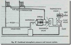
The desired vacuum in the heat emiHing units is obtained by “throttling” the supply steam with .the unit feed valves. The work ing principle of this system is shown in the elementary sketch found in Fig. 37.
In operation, when steam is raised in the boiler it passes through the steam main risers and supply valves .to the heat emit ting units.
The proper working of this system is obtained by an automatic device or trap which closes against the pressures of either steam or condensation and allows air .to pass out, but not the steam. The trap (Fig. 37) consists of three elements: (1) a diaphragm valve (point L); (2) a float valve (point A); and (3) a thermostatic valve (point F). Connection (R), in Fig. 37, connects the steam outlet of the boiler to the diaphragm. When there is no pressure in the boiler, diaphragm valve (L) is held closed by the spring.
When the fire in the boiler is started and the air in the boiler expands, the diaphragm is inflated and moves the valve spring to the right (against the action of the spring) which opens valve (L). This makes a direct opening through float valve (A) and thermo static valve (F), thus opening the system to the atmosphere. Valve (L) remains open as long as there is a fraction of an ounce pressure on the boiler. When steam forms and passes through the system, it drives all the air out of the system through the three open valves (L, A, and F).
The heat of the steam causes the expansion element of valve (F) to expand and close the valve, thus the system is filled only with steam.
The vacuum is obtained on the principle that the steam admitted to the radiators condenses while giving off heat through the radiator walls. This causes a tremendous reduction in volume of the steam remaining in the radiators, resulting in a pressure reduction in radiators, less than atmospheric-that is, a vacuum is formed. The steam condenses because of a reduction in tem perature below that corresponding to the pressure of the steam.
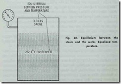
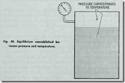
When the radiator gives off heat in heating the room, the temperature of the steam in the radiator is lowered. This reduction in temperature causes some of the steam to condense in a sufficient amount to restore equilibrium between temperature and pressure of the steam.
The pressure fa11s because the temperature falls. If a c1osed flask containing steam and water is allowed to stand for a length of time, the atmosphere being at a lower temperature than that inside, the flask will abstract heat from the steam and water, but the heat will leave the steam quicker than the water. The result is a continuous condensation of the steam and reevaporation of the water, during which process .the temperature of the whole mass and the boiling point is gradually lowered until the temperature inside of the flask is the same as that outside. This process is ac complished by a gradual decrea se in pressure. Figs. 38, 39 and 40 illustrate the effect of pressure on the boiling point.
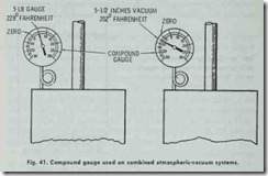
A one-pipe system may be converted into a combined system by replacing the air vent on the heat emitting units and making the piping absolutely tight. In this conversion, a “compound” gauge recording both pounds of steam and inches of vacuum is required (Fig. 41 ).
![Fig.-35.-Mechanical--vacuum--ejector[2] Fig.-35.-Mechanical--vacuum--ejector[2]](http://machineryequipmentonline.com/hvac-machinery/wp-content/uploads/2020/04/Fig.-35.-Mechanical-vacuum-ejector2_thumb.jpg)
![Fig.---36.--Mechanical---vacuum---ai[1] Fig.---36.--Mechanical---vacuum---ai[1]](http://machineryequipmentonline.com/hvac-machinery/wp-content/uploads/2020/04/Fig.-36.-Mechanical-vacuum-ai1_thumb.jpg)


![Fig.---39.---Reducing----the---press[1] Fig.---39.---Reducing----the---press[1]](http://machineryequipmentonline.com/hvac-machinery/wp-content/uploads/2020/04/Fig.-39.-Reducing-the-press1_thumb.jpg)

