Vapour compression systems
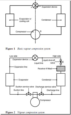
The basic refrigeration system comprises four major components (Figure 1):
1 The evaporator or cooling coil, which creates a cool surface to which heat may transfer from the refrigerated space or product and be absorbed by the cooling agent (refrigerant) circulated within.
2 The compressor, which circulates the cooling agent and changes its state by compression, creating a pressure differential at B.
3 The condenser, which provides a sufficient surface area to be able to reject the heat absorbed by the cooling agent or refrigerant, conveyed from the evaporator.
4 The expansion device or refrigerant metering control, which regulates
the flow of refrigerant to the evaporator and creates a pressure differential at A.
Some systems include a liquid receiver, which acts as a storage container for surplus refrigerant during normal operation and is able to retain the bulk of the system operating charge whilst certain service operations are performed.
Refrigerant is conveyed to and from these components by interconnecting pipework, as in Figure 2.
It will be seen from Figures 1 and 2 that the system is divided. The low side runs from the outlet of the expansion device to the inlet of the compressor, and the high side from the outlet or discharge of the compressor to the inlet of the expansion device. The compressor and expansion device are the two components which create a pressure differential within the system, and malfunction of either will affect the system operation.
Obviously, the presence of high and low pressures within the system necessitates the use of valves to isolate those pressures during service operations (Figure 2). These valves are known as service valves and, although the design and position of the valves may vary, their function remains the same.
