Thermal Resistance
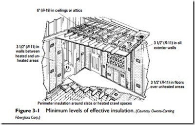
The R-value (thermal resistance) of a building material is its resistance to the flow of heat. As explained in the preceding subsection, the R-value is the reciprocal of the k-value or the C-value and rep- resents heat flow resistance expressed as a numerical value. The higher the R-value of a material (or a combination of materials in a wall, ceiling, floor, or roof), the greater its resistance to the flow of heat. The minimum recommended R-values are R-30 for an attic, R-11 for walls, R-19 for ceilings and raised floors, and R-42 for ductwork (Figure 3-1). Energy savings and lower fuel costs will result if insulation with an R-value higher than the recommended minimum is installed. This holds true for both new construction and existing structures.
Returning to the masonry wall illustrated in Table 3-2, you will note that all seven R-values have been added to produce the total resistance of a solid masonry wall (3.47). In other words, the total resistance to heat flow through a solid masonry wall of the type of construction illustrated in Table 3-2 is equal to the sum of the resistances of the wall components:
The total resistance (Rt) of a particular type of construction is used to determine its U-value, which represents the total insulating effect of a structural section. The U-value is the reciprocal of the total resistance (Rt). Using the data supplied for the masonry wall illustrated in Table 3-2, its U-value is determined as follows:
Overall Coefficient of Heat Transmission
The U-value, or U-factor (overall coefficient of heat transmission), represents the amount of heat (in Btu) that will pass through 1 square foot of a structural section per hour per degree Fahrenheit. This is the difference between the air on the inside and the air on the outside of the section. The U-value is the reciprocal of the sum of the thermal resistance values (R-values) of each element of the structural section. The total resistance (Rt) for the solid masonry wall illustrated in Table 3-2 is 3.47. Since the U-value is the reciprocal of Rt), the following is obtained:
The overall coefficient of heat transmission (U-value or U– factor) is used in the formula for calculating heat loss or heat gain. The use of this formula is described in Chapter 4 of this book (“Heating Calculations”) and in Chapter 9 of Volume 3 (“Air Conditioning Calculations”).
Condensation
Air will always contain a certain amount of moisture (water vapor), and the amount of moisture it contains will depend upon its temperature. Generally speaking, warm air is capable of containing more moisture than cold air.
Air will lose moisture in the form of condensation when its temperature falls below its dew point. The dew point is the temperature at which moisture begins to condense, in the form of tiny droplets or dew. Any reduction in temperature below the dew point will result in condensation of some of the water vapor present in the air.
The attic is one place where condensation often occurs. In the winter, the warm air from the occupied spaces leaks past the insulation on the top-floor ceiling and comes into contact with the cooler air in the attic. This causes the water vapor to condense. The moisture resulting from condensation works its way down through the ceiling and walls, eventually causing damage to the insulation, wood, and other building materials.
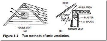
The solution to condensation in the attic is twofold. Adequate ventilation should be provided in the attic to remove the humid air. This can be accomplished by installing louvers at each end of the attic or in roof overhangs to provide cross ventilation (Figure 3-2). The louvers should have a total area of 1 ft2 for each 300 ft2 of attic floor space. For example, if the attic has an area of 900 ft2, the total louver area should be at least 3 ft2. In addition to suitable attic ventilation, you should install a vapor retarder between the rafters. This is particularly true if the attic is occupied or used extensively.
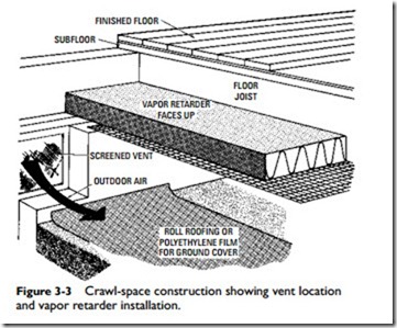
Foundation crawl spaces are also subject to condensation. A vapor retarder between the floor joists prevents excess moisture from accumulating and causing dampness and eventually damage to the structure. Ventilating the crawl space so that the humid air can be removed is also very effective. Finally, placing an insulating paper (e.g., roofing paper) on the ground will reduce the amount of moisture released by the soil (Figure 3-3).
Vapor Retarders
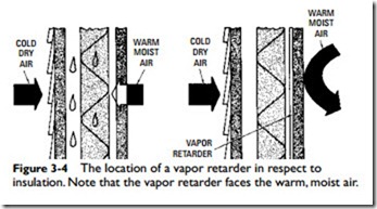
Insulation must be protected against moisture, or it will lose its ability to reduce thermal transmission. An unprotected insulation material will absorb moisture and lose its insulating value. This can
be very expensive, because the insulation must be replaced completely. In most cases there is no way to restore it to its original condition. A vapor retarder is a nonabsorbent material (e.g., asphalt laminated papers, aluminum foil, or plastic film), used to reduce the rate at which water vapor can move through a construction material (Figure 3-4). Note that it reduces the rate of water vapor movement. No material can completely stop moisture transfer. For that reason, the term vapor retarder has now replaced the older term vapor barrier, although the latter is still found in many publications and is widely used in the field by technicians. A vapor retarder protects the insulation by either completely enclosing it or by being installed between the insulation and the interior of the structure; that is to say, it is installed so that it faces inward toward the heated rooms and spaces.
Note
A vapor retarder is more accurately referred to as a vapor dif- fusion retarder (VDR) because the moisture it cannot stop is diffused through the material.
In addition to protecting insulation from absorbing moisture, a vapor retarder is an effective means of retaining moisture in the rooms and spaces in the structure or preventing it from entering these areas. As a result, it functions as an important factor in maintaining interior humidity conditions.
If you add insulation over an existing vapor retarder, you should make a number of cuts in the surface of the vapor retarder to avoid moisture entrapment. Remember, the “name of the game” is dry insulation. Take whatever measure necessary to protect it from moisture.


