OPERATION OF THE CIRCUIT
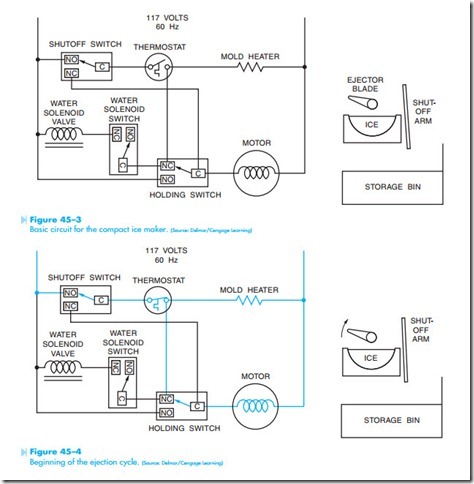
The basic circuit for the compact ice maker is shown in Figure 45–3. The circuit is shown during the freeze cycle. It is assumed that the mold has been filled with water and the thermostat contact is open. The shutoff arm is in its normal position, indicating that the holding bin is not full. Note the position of the ejector blade and the shutoff arm.
Figure 45–4 shows the circuit at the beginning of the ejection cycle. At this time, the thermostat has cooled sufficiently for its contact to close. A current path now exists through the mold heater and motor, and the ejector blades begin to turn.
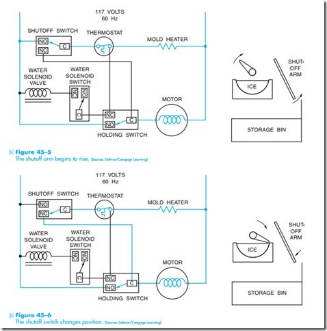
As the motor turns the ejector blades and timing cam, the holding switch changes position and the shutoff arm begins to rise, Figure 45–5. The function of the holding switch is to maintain the circuit until the cam returns to the freeze, or off, position.
In Figure 45–6, the timing cam causes the shut- off arm to rise and fall, making the shutoff switch change position. When the ejector blades reach the ice in the mold, the motor will stall until the ice cubes are thawed loose by the mold heater. Notice that the circuit to both the heater and motor has
been maintained by the holding switch. Note that it is possible for the thermostat to open its contact at any point in this process. If this should occur, power is turned off to the mold heater but maintained to the motor by the holding switch.
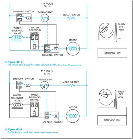
Near the completion of the first revolution of the ejector blades, the timing cam closes the water solenoid switch, Figure 45–7. Although the water solenoid switch is now closed, current cannot flow through the coil. As long as the thermostat contact is closed, the same voltage potential is applied to both sides of the water solenoid coil. Because there is no potential ifference across the coil, no current can flow and the water valve does not open to permit water flow into the mold.
At the end of the first revolution, Figure 45–8, the shutoff arm and ejector blades have returned to their normal position and the timing cam has reset
all cam-operated switches back to their normal position. Notice, however, that the thermostat contact has remained in the closed position, permitting the second revolution to begin.
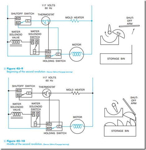
After the timing cam has rotated a few degrees, the holding switch again closes to maintain a current path to the motor and mold heater, Figure 45–9. The shutoff arm raises and changes the position of the shutoff switch. The continued rotation of the ejector blades dumps the ice into the holding bin.
During the second revolution, the increased tem- perature from the mold heater causes the thermo- stat contact to reopen, which deenergizes the heater, Figure 45–10. The holding contact, however, provides a continued current path to the motor. If the storage bin is full, the shutoff arm will not return to its normal position and the shutoff switch will not be reset.
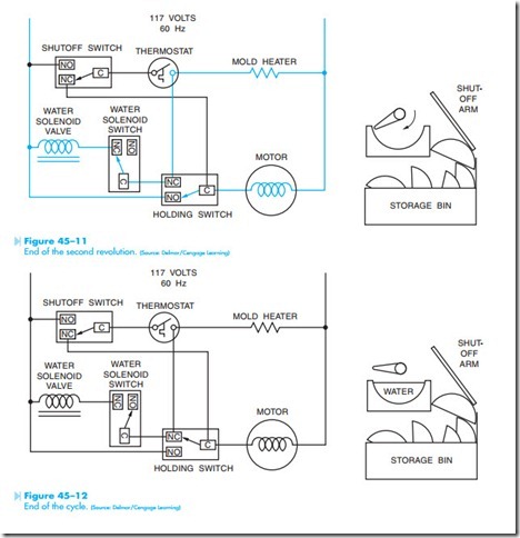
Near the completion of the second revolution, Figure 45–11, the timing cam again closes the water solenoid switch. A current path now exists through the solenoid coil and the mold heater. Although the solenoid coil and mold heater are now connected in series, the impedance of the solenoid coil is much higher than that of the heater. This permits most of the voltage, about 105 to 110 volts, to be applied across the coil causing it to energize and open the water valve.
The cycle ends when the timing cam reopens the water solenoid and holding switch, Figure 45–12. If the storage bin is full as shown in this illustration, a new ejection and refill cycle cannot begin until sufficient ice has been removed from the storage bin to permit the shutoff arm to return to its normal position.
