THE NEW MODEL COMPACT ICE MAKER
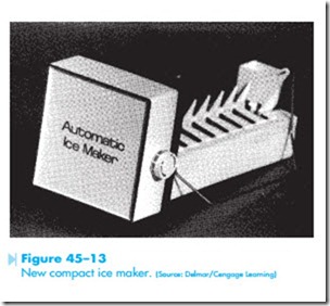
Although the new model compact ice maker, Figure 45–13, is very similar in design and operating principle to the original version just discussed, there are some significant differences. Some of these differences are listed below:
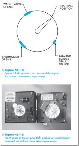
1. The ejector blades on the newer model stop at a different position, as shown in Figure 45–14. Also shown in Figure 45–14 is the position of the ejector blades when different actions occur during the ejection cycle.
2. The ejector blades make only one revolution instead of two during the ejection cycle.
3. Most of the new models have an external water level adjustment knob, Figure 45–13. Turning the knob moves a set of contacts in relation to its contact ring, permitting the fill time to be longer or shorter.
4. On the original model compact ice maker, the gear located on the front of the unit could be turned manually to advance the ice maker through different parts of the cycle. This gear should never be turned on the newer model. To do so will cause damage to the ice maker. The front gears of both the original and newer compact ice makers are shown in Figure 45–15.
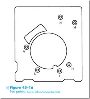
5. The new model compact provides test points on the plate located behind the front cover, Figure 45–16. It is possible to test different parts of the electrical circuit using a voltmeter and ohmmeter. The letters indicate the following test points:
• N = Neutral side of the line
• L = L1 (HOT) side of the line
• M = Motor connection
• H = Heater connection
• T = Thermostat connection
• V = Water valve connection
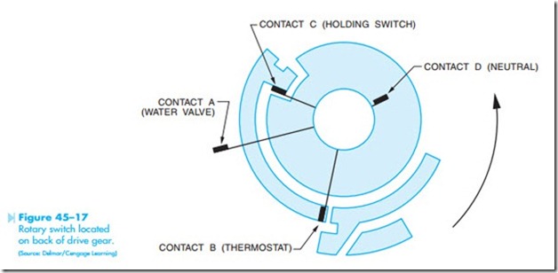
6. Probably the greatest difference lies in the electrical circuit itself. In this model, copper strips are laminated on an insulated plate
located on the back side of the drive gear. When the motor turns, it turns these copper strips also. Contacts ride against these copper strips and make or break connection to operate the circuit. A diagram of the copper strips and contacts is shown in Figure 45–17.
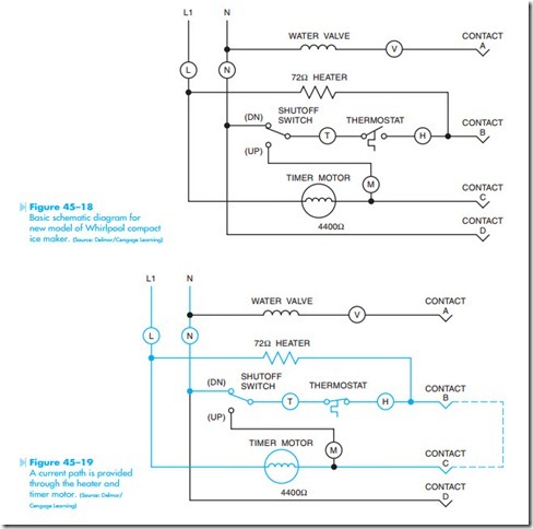
The basic electrical circuit for this unit is shown in Figure 45–18. Please note that the contact points A, B, C, and D correspond to the contacts shown in Figure 45–17. At this point, connection is made between contacts B and C.
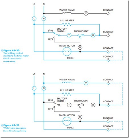
When the thermostat reaches approximately 17°F, its contact will close and produce a current path to both the motor and heater as shown in Figure 45–19. The motor begins to turn both the ejector blades and the copper strips located on the back of the main gear. At some point, contact between points B and C is broken and contact between points C and D is made, as shown in Figure 45–20. The ejector blades then stall against the ice. A current path is maintained to the motor between points C and D and a current path is maintained to the heater by the closed thermostat contact.
After the surface of the ice has been thawed by the heater, the ejector blades will begin to turn again. After the ejector blades have rotated approximately 180°, the thermostat contact opens,
Figure 45–14. As the blades continue to turn, the shutoff arm rises and lowers and the copper strips advance until connection is made between contacts A and B, Figure 45–21. This provides a current path through the mold heater to the water solenoid valve. Because the coil of the solenoid has a much higher impedance than the mold heater, most of the line voltage will be dropped across the valve, causing it to open and refill the mold. The ejector blades will continue to turn until they reach the end of the cycle and the circuit returns to its original condition as shown in Figure 45–18.
