FAN CYCLE CONTROL
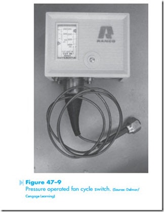
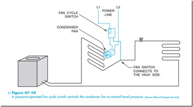
Another common method of increasing head pressure is by controlling the amount of air across the condenser. Air-cooled condensers of large refrigeration units and air conditioners employ a fan to increase airflow across them. The increased airflow permits a greater amount of heat to be removed. During periods that the ambient temperature is so low that the head pressure drops below a certain amount, a fan cycle switch can be used to dis- connect power to the condenser fan, Figure 47–9. The switch shown in Figure 47–9 is pressure
operated. It is connected in the high side of the unit, Figure 47–10. The switch can be adjusted for the amount of pressure required to turn the fan on and off. A typical setting for refrigerant R12 is 125 psi turn off and 175 psi turn on. At pressures greater than 175 psi a set of electrical contacts inside the switch close and connect the condenser fan to the power line. If the high side pressure should drop below 125 psi, the contacts will open and turn off the condenser fan. The pressure differential prevents rapid cycling of the condenser fan motor. The fan cycle switch will not hinder operation during warm months and will provide good operation during cold months.
The fan cycle switch is relatively inexpensive and can be added to an existing system with very little trouble. Generally no alterations to the piping system are required. There is one potential problem
with this type of head pressure control. The pressure differential between fan turn on and turn off can cause erratic operation of the expansion valve.
Units that employ more than one condenser fan will often have one fan controlled by pressure and the others controlled by temperature-sensitive switches. The fans will be set to turn on or off in stages. One temperature switch, for example, may turn a fan off at 75°F and another switch may turn a fan off at 65°F. This helps maintain a more constant head pressure. When temperature switches are used, the temperature sensing element is generally connected to the liquid line.
Variable Speed Control
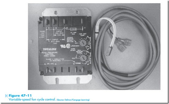
Another type of fan cycle control employs a solid state device called a triac to control motor speed, Figure 47–11. The triac has the ability to control the output voltage applied to the motor. Refer to Unit 56 for more information concerning the operation of a triac. Some controls vary the output voltage applied to the condenser fan in accord with the temperature of the liquid refrigerant line, and others sense ambient
temperature. A thermistor is used to sense the temperature. A decrease of temperature causes the unit to reduce the voltage applied to the condenser fan motor causing it to slow down. As the temperature increases the output voltage increases permitting the motor to increase speed. A chart illustrating typical voltage and temperature relationships for a control that senses liquid line temperature is shown in Figure 47–12. The voltage/temperature relationship can be changed to some degree by changing the type thermistor used to sense the temperature. Notice on the chart that at temperatures below about 75°F the motor is turned off and at temperatures above about 115°F full output voltage is applied to the motor.
The variable speed control helps eliminate some of the pressure differential problems encountered with fan cycle controls that simply turn on or off. A typical connection diagram for this type control is shown in Figure 47–13.


