CONDENSER FLOODING
Condenser flooding is accomplished by placing a pressure operated valve in the refrigerant line between the condenser and metering valve. More than one method can be employed to accomplish this. Flooding the condenser with liquid refrigerant has the effect of covering the condenser with a plastic blanket. This causes an increase in condenser temperature and a corresponding increase in head pressure. To accomplish condenser flooding, the unit must contain enough liquid refrigerant to flood the condenser. This calls for a large charge of refrigerant and some means of storing it. Units intended to use condenser flooding contain a receiver to hold the excess refrigerant.
Nonadjustable Head Pressure Valve
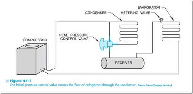
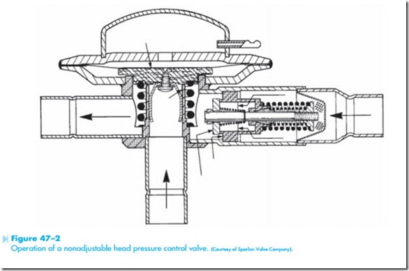
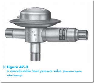
Figure 47–1 illustrates the connection of a nonadjustable head pressure control valve. A line drawing of the valve is shown in Figure 47–2. The valve’s main port is between the condenser and receiver. As long as receiver pressure remains above a certain level the bypass between discharge and receiver portions of the valve are closed. If the receiver pressure should drop, such as would be the case with low ambient temperature, the spring loaded valve over- comes the receiver pressure and hot gas begins to flow through the discharge portion of the valve. Low receiver pressure also causes the valve to decrease the flow from the condenser, causing refrigerant to backup in the condenser. This has the effect of decreasing the surface area of the condenser causing an increase in temperature and a corresponding
increase in pressure. This valve maintains an almost constant pressure and function well in temperatures of up to about –40°F. A nonadjustable head pressure control valve is shown in Figure 47–3.
Adjustable Head Pressure Valve
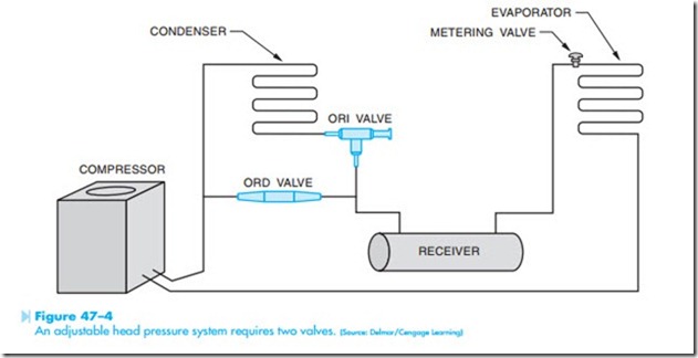
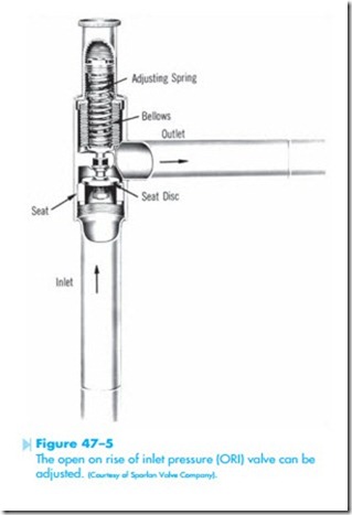
Adjustable head pressure systems generally require the use of two valves. One valve opens on rise of inlet pressure (ORI) and the other opens on rise of differential pressure (ORD). A basic piping connection for the adjustable head pressure system is shown in Figure 47–4. An illustration of the ORI valve is shown in Figure 47–5. The ORI valve is an inlet pressure regulating valve that responds to changes in the condenser pressure. Note that both the inlet and outlet pressures are against the seat disc. One tends to cancel the effects of the other. In warm weather the condenser pressure is greater than the receiver pressure, which causes the valve to open and permit refrigerant to flow through the condenser.
The ORD valve provides a bypass around the con- denser. An illustration of the ORD valve is shown in Figure 47–6. The compressor head pressure acts to open the ORD valve and the receiver pressure and
spring tend to keep the valve closed. If the receiver pressure should drop due to low ambient temperature, two actions take place.
1. The ORI valve begins to close and reduce the flow of refrigerant through the condenser.
2. The ORD valve begins to open and permit the hot gas to bypass the condenser and flow to the receiver.
The reduced flow of refrigerant through the con- denser causes an increase in temperature and pressure. An ORI valve is shown in Figure 47–7 and an ORD valve is shown in Figure 47–8.
