Reaction turbines
The primary features of the reaction turbine are:
i. only part of the overall pressure drop has occurred up to turbine entry, the remaining pressure drop takes place in the turbine itself;
ii. the flow completely fills all of the passages in the runner, unlike the Pelton turbine where, for each jet, only one or two of the buckets at a time are in contact with the water;
iii. pivotable guide vanes are used to control and direct the flow;
iv. a draft tube is normally added on to the turbine exit; this is considered as an integral part of the turbine.
The pressure of the water gradually decreases as it flows through the runner and the reaction from this pressure change earns this type of turbine its appellation.
The Francis turbine
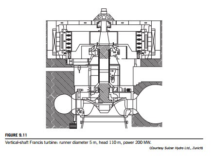
The majority of Francis turbines are arranged so that the axis is vertical (some smaller machines can have horizontal axes). Figure 9.11 illustrates a section through a vertical-shaft Francis turbine with a runner diameter of 5 m, a head of 110 m, and a power rating of nearly 200 MW. Water enters via a spiral casing called a volute or scroll that surrounds the runner. The area of cross- section of the volute decreases along the flow path in such a way that the flow velocity remains constant. From the volute, the flow enters a ring of stationary guide vanes, which direct it onto the runner at the most appropriate angle.
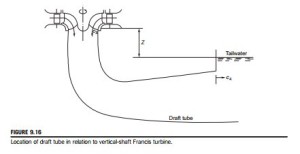
In flowing through the runner, the angular momentum of the water is reduced and work is supplied to the turbine shaft. At the design condition, the absolute flow leaves the runner axially (although a small amount of swirl may be countenanced) into the draft tube and, finally, the flow enters the tailrace. It is essential that the exit of the draft tube is submerged below the level of the water in the tailrace in order that the turbine remains full of water. The draft tube also acts as a diffuser; by careful design, it can ensure maximum recovery of energy through the turbine by significantly reducing the exit kinetic energy.
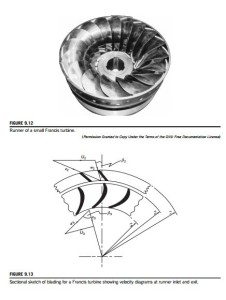
Figure 9.12 shows the runner of a small Francis turbine and Figure 9.13 is a sectional view of the turbine together with the velocity triangles at inlet to and exit from the runner at mid-blade height. At inlet to the guide vanes, the flow is in the radial/tangential plane, the absolute velocity is c1, and the absolute flow angle is α1. Thus,
The flow is turned to angle α2 and velocity c2, the absolute condition of the flow at entry to the runner. By vector subtraction, the relative velocity at entry to the runner is found, i.e., w2 5 c2 2 U2. The relative flow angle β2 at inlet to the runner is defined as
Further inspection of the velocity diagrams in Figure 9.13 reveals that the direction of the velocity vectors approaching both guide vanes and runner blades are tangential to the camber lines at the leading edge of each row. This is the ideal flow condition for “shockless” low loss entry, although an incidence of a few degrees may be beneficial to output without a significant extra loss penalty. At vane outlet some deviation from the blade outlet angle is to be expected (see Chapter 3). For
these reasons, in all problems concerning the direction of flow, it is clear that the angle of the fluid flow is important and not the vane angle as is often quoted in other texts.
At outlet from the runner, the flow plane is simplified as though it were actually in the radial/ tangential plane. This simplification will not affect the subsequent analysis of the flow, but it must be conceded that some component of velocity in the axial direction does exist at runner outlet.
The water leaves the runner with a relative flow angle β3 and a relative flow velocity w3. The absolute velocity at runner exit is found by vector addition, i.e., c3 5 w3 1 U3. The relative flow angle, β3, at runner exit is given by
![]() In this equation it is assumed that some residual swirl velocity cθ3 is present (cr3 is the radial velocity at exit from the runner). In most simple analyses of the Francis turbine, it is assumed that there is no exit swirl. Detailed investigations have shown that some extra counter-swirl (i.e., acting so as to increase Δcθ) at the runner exit does increase the amount of work done by the fluid with- out a significant reduction in turbine efficiency.
In this equation it is assumed that some residual swirl velocity cθ3 is present (cr3 is the radial velocity at exit from the runner). In most simple analyses of the Francis turbine, it is assumed that there is no exit swirl. Detailed investigations have shown that some extra counter-swirl (i.e., acting so as to increase Δcθ) at the runner exit does increase the amount of work done by the fluid with- out a significant reduction in turbine efficiency.
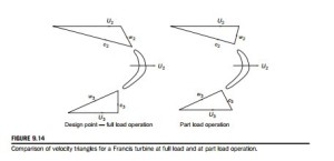
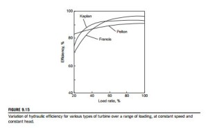
When a Francis turbine is required to operate at part load, the power output is reduced by swiveling the guide vanes to restrict the flow, i.e., Q is reduced, while the blade speed is maintained constant. Figure 9.14 compares the velocity triangles at full load and at part load from which it will be seen that the relative flow at runner entry is at a high incidence and at runner exit the absolute flow has a large component of swirl. Both of these flow conditions give rise to high head losses. Figure 9.15 shows the variation of hydraulic efficiency for several types of turbine, including the Francis turbine, over the full load range at constant speed and constant head.
It is of interest to note the effect that swirling flow has on the performance of the following diffuser. The results of an extensive experimental investigation made by McDonald, Fox, and van Dewoestine (1971) showed that swirling inlet flow does not affect the performance of conical diffusers, which are well designed and give unseparated or only slightly separated flow when the flow through them is entirely axial. Accordingly, part load operation of the turbine is unlikely to give adverse diffuser performance.
Basic equations
Euler’s turbine equation, Eq. (1.18c), in the present notation, is written as
where ΔHN is the loss of head due to friction in the volute and guide vanes and p2 is the absolute static pressure at inlet to the runner.
At runner outlet, the energy in the water is further reduced by the amount of specific work ΔW and by friction work in the runner, gΔHR and this remaining energy equals the sum of the pressure potential and kinetic energies:
where p3 is the absolute static pressure at runner exit.
By differencing Eqs (9.17) and (9.18), the specific work is obtained:
where p02 and p03 are the absolute total pressures at runner inlet and exit.
Figure 9.16 shows the draft tube in relation to a vertical-shaft Francis turbine. The most important dimension in this diagram is the vertical distance (z 5 z3) between the exit plane of the runner and the free surface of the tailrace. The energy equation between the exit of the runner and the tail- race can now be written as
The overall efficiency is given by ηo = ηmηH. For very large turbines (e.g., 500-1000 MW), the mechanical losses are then relatively small, η-100% and effectively .
For the Francis turbine, the ratio of the runner tip speed to the jet velocity, v 5 U2/c1, is not as critical for high-efficiency operation as it is for the Pelton turbine and can lie in a fairly wide range, e.g ., 0.6 # v # 0.95. In most applications, the Francis turbine is used to drive a synchronous genera- tor and the rotational speeds chosen are those appropriate to either 50 or 60 cycles per second. The speed must then be maintained constant.
It is possible to obtain part load operation of the turbine by varying the angle of the guide vanes. The guide vanes are pivoted and set to an optimum angle via a gearing mechanism. However, part load operation normally causes a whirl velocity to be set up in the flow downstream of the runner causing a reduction in efficiency. The strength of the vortex may be enough to cause a cavitation bubble to form along the axis of the draft tube (see Section 9.8).
EXAMPLE 9.3
In a vertical-shaft Francis turbine, the available head at the inlet flange is 150 m of water and the vertical distance between the runner and the tailrace is 2.0 m. The runner tip speed is 35 m/s, the meridional velocity of the water through the runner is constant at 10.5 m/s, the flow leaves the runner without whirl and the velocity at exit from the draft tube is 3.5 m/s.
The hydraulic losses for the turbine are as follows:
Determine
a. the specific work, ΔW, and the hydraulic efficiency, ηh, of the turbine;
b. the absolute velocity, c2, at runner entry;
c. the pressure head (relative to the tailrace) at inlet to and exit from the runner;
d. the absolute and relative flow angles at runner inlet; the flow discharged by the turbine is 20 m3/s and the power specific speed is 0.8 (rad), the speed of rotation and diameter of the runner.
Solution
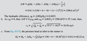
a. From Eqs (9.18) and (9.20), we can find the specific work:
Again, using Eq. (9.20), the pressure head (relative to the tailrace) at runner exit is
Note: The minus sign for H3 indicates that the pressure is below the atmospheric level. This is a matter of considerable importance in the design and operation of hydraulic turbomachinery and is considered in further detail under Section 9.8 later in this chapter.
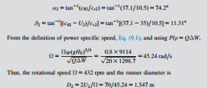
d. The flow angles at runner inlet are now obtained as follows:
The pump turbine
The pump turbine is an example of a system capable of providing large reserves of power with a very short start-up time and its design is generally based on the Francis turbine. It is, essentially, a reversible turbomachine employing two large reservoirs, one at high level able to generate power from the turbines in the daytime when the demand for electricity is high and the other at low level used to store the water which is pumped back at night when the demand for electricity is low. The plant is usually referred to as a pumped storage scheme. (For further technical details, consult Stelzer and Walters (1977) or go to URL www.usbr.gov/pmts/hydraulics_lab/pubs/EM/EM39.pdf).
EXAMPLE 9.4
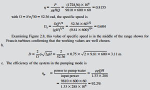
A modern pumped storage scheme, the Gwynedd plant at Llanberis, North Wales, consists of six Francis turbines with a total power output P 5 1728 MW, a volume flow rate Q 5 60 m3/s for each turbine, a head H 5 600 m at full capacity, operating at a rotational speed of Ω 5 500 rpm. When pumping the water back to the upper reservoir, the demand on the electricity supply is 33% greater than it was in the turbine mode.
Determine
a. the efficiency of the turbines and their specific speed, comparing the value you obtain with the range of values shown in Figure 2.8; comment on the suitability of these turbines for the task;
b. the diameter of the turbines assuming a peripheral velocity factor (PVF) for the turbines of 0.75;
c. the efficiency of the system in the pumping mode.
Solution
a. The efficiency of each turbine is
Related posts:
Incoming search terms:
- primary features of a reaction turbine
- across the runner of pelton turbine absolute velocity remains constant
- what is meant by shockless entry
- shokless entry to turbine impact which efficiency mechanical or hydraulic
- shocless entry in hydraulic tutbine increaes the effciency
- shockless entry of water in hydraulic turbine is of much significant from the standpoint of
- Shockless entry in turbine Is not their then which efficiency is effected
- shockless entry in turbine
- shockless entry in hydraulic turbine
- shockless entry hydraulic turrbined
- shockless entry and shockless exit in turbine
- shockless enntry of water in hydraulic turbine is of much significant from the standpoint of
- shock less entry and hydraulic efficiency
- hydraulic reaction turbine
- hydraulic efficiency of reaction turbine
- effect of shockless entry on mechanical efficiency of hydraulic machine
- as area of casing of francis turbine gradually decreases velocity remains constant why
- ‘Shockless entry’ of water in hydraulic turbines is of much significance from the standpoint of
