Application of CFD to the design of hydraulic turbines
With such a long history, the design of hydraulic turbines still depends very much on the experience gained from earlier designs. According to Drtina and Sallaberger (1999), the use of computational fluid dynamics (CFDs) for predicting the flow in these machines has brought further substantial improvements in their hydraulic design and resulted in a more complete understanding of the flow processes and their influence on turbine performance. Details of flow separation, loss sources, and loss distributions in components both at design and off-design as well as detecting low-pressure levels associated with the risk of cavitation are now amenable to analysis with the aid of CFD.
Drtina and Sallaberger presented two examples where the application of CFD resulted in a better understanding of complex flow phenomena. Generally, this better knowledge of the flow has resulted either in design improvements to existing components or to the replacement of components by a completely new design.
The Wells turbine
Introduction
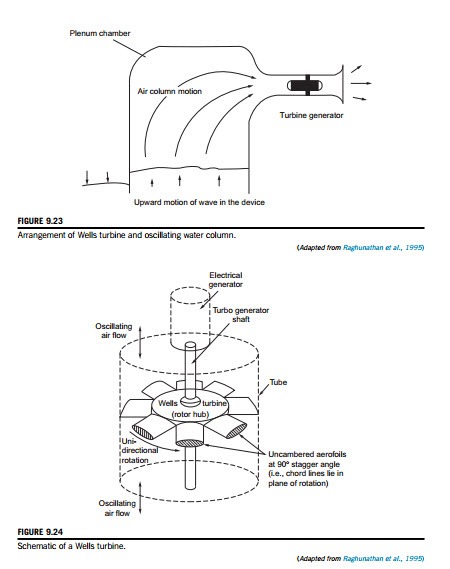
Numerous methods for extracting energy from the motion of sea waves have been proposed and investigated since the late 1970s. The problem is in finding an efficient and economical means of converting an oscillating flow of energy into a unidirectional rotary motion for driving electrical generators. A novel solution of this problem is the Wells turbine (Wells, 1976), a version of the axial-flow turbine. For countries surrounded by the sea, such as the British Isles and Japan to mention just two, or with extensive shorelines like the United States, wave energy conversion is an attractive proposition. Energy conversion systems based on the oscillating water column and the Wells turbine have been installed at several locations (Islay in Scotland and Trivandrum in India). Figure 9.23 shows the arrangement of a turbine and generator together with the oscillating column of seawater. The cross-sectional area of the plenum chamber is made very large com- pared to the flow area of the turbine so that a substantial air velocity through the turbine is attained.
One version of the Wells turbine consists of a rotor with eight uncambered aerofoil section blades set at a stagger angle of 90o (i.e., with their chord lines lying in the plane of rotation).
A schematic diagram of such a Wells turbine is shown in Figure 9.24. At first sight, the arrangement might seem to be a highly improbable means of energy conversion. However, once the blades have attained design speed, the turbine is capable of producing a time-averaged positive power output from the cyclically reversing airflow with a fairly high efficiency. According to Raghunathan, Curran, and Whittaker (1995), peak efficiencies of 65% have been measured at the experimental wave power station on Islay. The results obtained from a theoretical analysis by Gato and de O Falca`o (1984) showed that fairly high values of the mean efficiency, on the order of 70-80%, may be attained in an oscillating flow “with properly designed Wells turbines.”.
Operating principles
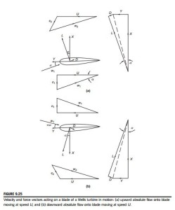
Figure 9.25(a) shows a blade in motion at the design speed U in a flow with an upward, absolute axial velocity c1. It can be seen that the relative velocity w1 is inclined to the chord line of the blade at an angle α. According to classical aerofoil theory, an isolated aerofoil at an angle of incidence α to a free stream will generate a lift force L normal to the direction of the free stream. In a viscous fluid, the aerofoil will also experience a drag force D in the direction of the free stream. These lift and drag forces can be resolved into the components of force X and Y as indicated in Figure 9.25(a), i.e.,
The student should note, in particular, that the force Y acts in the direction of blade motion, giving positive work production.
For a symmetrical aerofoil, the direction of the tangential force Y is the same for both positive and negative values of α, as indicated in Figure 9.25b. If the aerofoils are secured to a rotor drum to form a turbine row, as in Figure 9.24, they will always rotate in the direction of the positive tangential force regardless of whether the air is approaching from above or below. With a time- varying, bidirectional airflow, the torque produced will fluctuate cyclically but can be smoothed to a large extent by means of a high inertia rotor-generator.
It will be observed from the velocity diagrams that a residual swirl velocity is present for both directions of flow. It was suggested by Raghunathan et al. (1995) that the swirl losses at turbine exit can be reduced by the use of guide vanes.
Two-dimensional flow analysis
The performance of the Wells turbine can be predicted by means of blade element theory. In this analysis, the turbine annulus is considered to be made up of a series of concentric elementary rings, each ring being treated separately as a two-dimensional cascade.
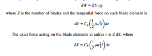
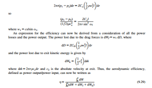
The power output from an elementary ring of area 2πr dr is given by
and where Cx, Cy are the axial and tangential force coefficients, respectively. Now the axial force on all the blade elements at radius r can be equated to the pressure force acting on the ele- mentary ring:
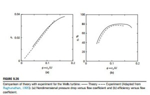
The predictions for nondimensional pressure drop p* and aerodynamic efficiency η determined by Raghunathan et al. (1995) are shown in Figure 9.26(a) and (b), respectively, together with exper- imental results for comparison.
Design and performance variables
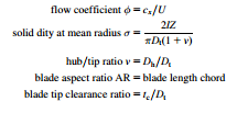
The primary input for the design of a Wells turbine is the air power based upon the pressure amplitude (p1 2 p2) and the volume flow rate Q at turbine inlet. The performance indicators are the pressure drop, power, and efficiency, and their variation with the flow rate. The aerodynamic design and consequent performance is a function of several variables that have been listed by Raghunathan. In nondimensional form, these are
and also blade thickness ratio, turbulence level at inlet to turbine, frequency of waves, and the relative Mach number. It was observed by Raghunathan, Setoguchi, and Kaneko (1987) that the Wells turbine has a characteristic feature that makes it significantly different from most turbomachines: the absolute velocity of the flow is only a (small) fraction of the relative velocity. It is theoretically possible for transonic flow conditions to occur in the relative flow resulting in additional losses due to shock waves and an interaction with the boundary layers leading to flow separation. The effects of these variables on the performance of the Wells turbine have been considered by Raghunathan (1995) and a summary of some of the main findings follow.
Effect of flow coefficient
The flow coefficient φ is a measure of the angle of incidence of the flow and the aerodynamic forces developed are critically dependent upon this parameter. Typical results based on predictions and experiments of the nondimensional pressure drop p* 5 Ωp=ðρω2D2Þ and efficiency are shown in Figure 9.26. For a Wells turbine, a linear relationship exists between pressure drop and the flow rate (Figure 9.26(a)), and this fact can be employed when making a match between a turbine and an oscillating water column that also has a similar characteristic.
The aerodynamic efficiency η (Figure 9.26(b)) is shown to increase up to a certain value, after which it decreases, because of boundary layer separation.
Effect of blade solidity
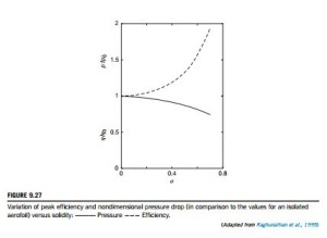
The solidity is a measure of the blockage offered by the blades to the flow of air and is an important design variable. The pressure drop across the turbine is, clearly, proportional to the axial force acting on the blades. An increase of solidity increases the axial force and likewise the pressure
drop. Figure 9.27 shows how the variations of peak efficiency and pressure drop are related to the amount of the solidity.
Raghunathan gives correlations between pressure drop and efficiency with solidity:
where the subscript 0 refers to values for a two-dimensional isolated aerofoil (σ 5 0). A correlation between pressure drop and solidity (for σ . 0) was also expressed as
Effect of hub-tip ratio
The hub-tip ratio v is an important parameter as it controls the volume flow rate through the turbine but also influences the stall conditions, the tip leakage, and, most importantly, the ability of the turbine to run up to operating speed. Values of v , 0.6 are recommended for design.
The starting behavior of the Wells turbine
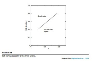
When a Wells turbine is started from rest, the incoming relative flow will be at 90o to the rotor blades. According to the choice of the design parameters, the blades could be severely stalled and, consequentially, the tangential force Y will be small and the acceleration negligible. In fact, if and when this situation occurs, the turbine may accelerate only up to a speed much lower than the design operational speed, a phenomenon called crawling. The problem can be avoided either by choosing a suitable combination of hub-tip ratio and solidity values at the design stage or by some other means, such as incorporating a starter drive. Values of hub-tip ratio and solidity that have been found to allow self-starting of the Wells turbine are indicated in Figure 9.28.
Pitch-controlled blades
Some appreciable improvements have been made in the performance of the Wells turbine as a result of incorporating pitch-controlled blades into the design. The efficiency of the original Wells turbine had a peak of about 80%, but the power output was rather low and the starting performance was poor. One reason for the low-power output was the low tangential force Y and low flow coeffi- cient φ as a consequence of the fixed-blade geometry.
A turbine with self-pitch-controlled blades
Performance enhancement of the Wells turbine reported by Kim et al. (2002) was achieved by incorporating swivelable vanes instead of fixed vanes in an experimental test rig. The method they
devised used symmetrical blades that pivot about the nose, whose pitch angle changes by a small amount as a result of the varying aerodynamic forces developed by the oscillating flow. This change to the turbine configuration enables a higher torque and efficiency to be obtained from the reciprocating airflow. According to the authors, the turbine is geometrically simpler and would be less expensive to manufacture than some earlier methods using “active” pitch-controlled blades, e.g., Sarmento, Gato, and de O Falca`o (1987) and Salter (1993).
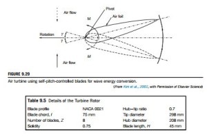
The working principle with self-pitch-controlled blades is illustrated in Figure 9.29. This shows one of the turbine blades fixed to the hub by a pivot located near the leading edge, allowing the blade to move between two prescribed limits, 6 γ. An aerofoil set at a certain angle of incidence experiences a pitching moment about the pivot, which causes the blade to flip. In this new position, the blade develops a higher tangential force and torque at a lower rotational speed than was obtained with the original fixed-blade design of the Wells turbine.
Kim et al., using a piston-driven wind tunnel, measured the performance characteristics of the turbine under steady flow conditions. To determine its running and starting characteristics, a quasi- steady computer simulation of the oscillating through-flow was used together with the steady state characteristics. Details of the turbine rotor are given in Table 9.5.
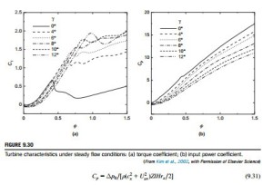
The turbine characteristics under steady flow conditions were determined in the form of the out- put torque coefficient, Cτ, and the input power coefficient, CP, against the flow coefficient, φ 5 cx/ Uav, defined as
where τ0 is the output torque and Δp0 is the total pressure difference across the turbine.
Figure 9.30(a) shows the Cτ versus φ characteristics for the turbine for various blade-setting angles. The solid line (γ 5 0o) represents the result obtained for the original, fixed-blade Wells tur- bine. For values of γ . 0o, Cτ decreases with increasing γ in the stall-free zone but, beyond the original stall point for γ 5 0, much higher values of Cτ were obtained.
Figure 9.30(b) shows the Cp versus φ characteristics for the turbine for various blade-setting angles. This figure indicates that for γ . 0o, the input power coefficient, Cp, is lower than the case where γ 5 0o for all values of φ. Clearly, this is due to the variation in the rotor blade-setting angle.
The instantaneous efficiency of the turbine is given by
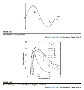
Using the measured characteristics for Cτ and Cp and assuming a sinusoidal variation of the axial velocity with a different maximum amplitude2 for each half cycle, as shown in Figure 9.31,
the mean efficiency of the cycle can be computed. Figure 9.32 shows the mean efficiency as a function of the flow coefficient φ for a range of γ values with cxi 5 0.6cxo.
Compared to the basic Wells turbine (with γ 5 0o), the optimum result for γ 5 10o shows an improved mean efficiency and an optimum flow coefficient of about 0.4. It is apparent that further field testing would be needed to prove the concept.
Further work
Energetech in Sydney, Australia, began (circa 2003) the design of a half-scale test turbine, which will be used for more detailed flow studies and to test new blade-hub arrangements.
Also, a full-scale 1.6 m diameter variable-pitch turbine has been constructed for use at the proto- type wave energy plant at Port Kembla, New South Wales, Australia. Studies of derivatives of the Wells turbine are also being undertaken at research centers in the United Kingdom, Ireland, Japan, India, and other countries. It is still not clear which type of blading or which pitch- control system will prevail. Kim et al. (2001) attempted a comparison of five derivatives of the Wells turbine using steady flow data and numerical simulation of an irregular wave motion. However, at present a “best” type has still not emerged from a welter of data. A final conclusion must await the outcome of further development and the testing of prototypes subjected to real sea wave conditions.
