Cavitation in hydraulic turbines
A description of the phenomenon of cavitation with regard to pumps was given in Chapter 7. In hydraulic turbines, where reliability, long life, and efficiency are all very important, the effects of cavitation must be considered. Two types of cavitation may be in evidence:
a. on the suction surfaces of the runner blades at outlet that can cause severe blade erosion;
b. a twisting “rope type” cavity that appears in the draft tube at off-design operating conditions.
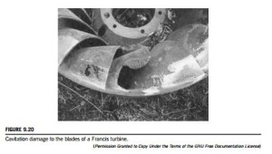
Cavitation in hydraulic turbines can occur on the suction surfaces of the runner blades where the dynamic action of the blades acting on the fluid creates low-pressure zones in a region where the static pressure is already low. Hydraulic turbines are designed to run for many years with very little maintenance. However, if cavitation does occur, then pitting of the surfaces, fatigue cracking, and partial collapse of the blades will reduce performance. Figure 9.20 shows extensive damage due to cavitation of a Francis runner.
Cavitation will commence when the local static pressure is less than the vapor pressure of the water, i.e., where the head is low, the velocity is high and the elevation, z, of the turbine is set too high above the tailrace. For a turbine with a horizontal shaft, the lowest pressure will be located in the upper part of the runner, which could be of major significance in large machines. Fortunately, the runners of large machines are, in general, made so that their shafts are orientated vertically, lessening the problem of cavitation occurrence.
The cavitation performance of hydraulic turbines can be correlated with the Thoma coefficient, σ, defined as
where HS is the net positive suction head (NPSH), the amount of head needed to avoid cavitation, the difference in elevation, z, is defined in Figure 9.16 and pv is the vapor pressure of the water. The Thoma coefficient was, strictly, originally defined in connection with cavitation in turbines and its use in pumps is not appropriate (see Yedidiah, 1981). It is to be shown that σ represents the fraction of the available head HE, which is unavailable for the production of work. A large value of σ means that a smaller part of the available head can be utilized. In a pump, incidentally, there is no direct connection between the developed head and its suction capabilities, provided that cavitation does not occur, which is why the use of the Thoma coefficient is not appropriate for pumps.
From the energy equation, Eq. (9.20), this can be rewritten as
so that when p3 5 pv, then HS is equal to the right-hand side of Eq. (9.24).
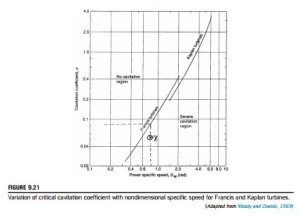
Figure 9.21 shows a widely used correlation of the Thoma coefficient plotted against specific speed for Francis and Kaplan turbines, approximately defining the boundary between no cavitation and severe cavitation. In fact, there exists a wide range of critical values of σ for each value of specific speed and type of turbine due to the individual cavitation characteristics of the various runner designs. The curves drawn are meant to assist preliminary selection procedures. An alternative method for avoiding cavitation is to perform tests on a model of a particular turbine in which the value of p3 is reduced until cavitation occurs or a marked decrease in efficiency becomes apparent. This performance reduction would correspond to the production of large-scale cavitation bubbles. The pressure at which cavitation erosion occurs will actually be at some higher value than that at which the performance reduction starts.
For the centerline cavitation that appears downstream of the runner at off-design operating conditions, oscillations of the cavity can cause severe vibration of the draft tube. Young (1989) reported some results of a “corkscrew” cavity rotating at 4 Hz. Air injected into the flow both stabilizes the flow and cushions the vibration.
EXAMPLE 9.7
Using the data for the Francis turbine given in Example 9.3 and the atmospheric pressure is 1.013 bar, and the water is at 25oC, determine the NPSH for the turbine. Hence, using Thoma’s coefficient and the data shown in Figure 9.21, determine whether cavitation is likely to occur. Verify the result using Wislicenus’s criterion, the result given in Eq. (2.23b).
Solution
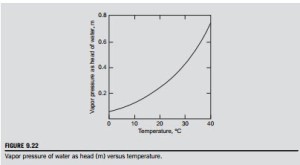
From tables of fluid properties, e.g., Rogers and Mayhew (1995), or using the data of Figure 9.22, the vapor pressure for water corresponding to a temperature of 25oC is 0.03166 bar. From the definition of NPSH, Eq. (9.24), we obtain
Thus, from Eq. (9.24) with HE 5 150 m, then Thoma’s coefficient is, σ 5 HS/HE 5 8.003/ 150 5 0.05336.
At the value of Ωsp 5 0.8 given as data, the value of the critical Thoma coefficient σc corresponding to this is 0.083 from Figure 9.21. From the fact that σ , σc, then the turbine will cavitate. The point X in Figure 9.21 is the intercept of σc and Ωsp in the severe cavitation zone.
From the definition of the suction specific speed,
According to Eq. (2.23b), when ΩSS exceeds 4.0 (rad) cavitation can occur, giving further confirmation of the above conclusion.
Connection between Thoma’s coefficient, suction specific speed, and specific speed The definitions of suction specific speed ΩSS and specific speed Ωs are
Exercise
Verify the value of Thoma’s coefficient in Example 9.5 using the values of power specific speed, efficiency, and suction specific speed given or derived.
We use as data ΩSS 5 7.613, ΩSP 5 0.8, and ηH 5 0:896 so that, from Eq. (2.16),
This value corresponds to point X shown in Figure 9.21 and corroborates the previous conclusion that cavitation will occur.
Avoiding Cavitation
By rearranging Eq. (9.24) and putting σ 5 σc, a critical value of z can be derived on the boundary curve between cavitation and no cavitation. Thus,
This means that the turbine would need to be submerged to a depth of 3.5 m or more below the surface of the tailwater and, for a Francis turbine, would lead to problems with regard to construction and maintenance. Equation (9.24) shows that the greater the available head HE at which a turbine operates, the lower it must be located relative to the surface of the tailrace.
Controversially, some manufacturers might allow for some cavitation damage to occur in large turbines, balancing this against the extra cost. A difficult choice!
Peripheral velocity factor
This is a most useful concept which is often used to verify (and calculate) the size of pumps and turbines. For a pump impeller or for a turbine runner, the PVF is defined as
where U2 is the peripheral velocity or blade tip speed (ΩD2=2) and H is the net head delivered by the pump or the effective head supplied to a turbine. Thus, from these expressions, we get
assuming all the parameters are at the respective maximum efficiency condition (BEP).
For the various main types of hydraulic turbine, the approximate values of PVF are as follows:
Selecting the right turbine
The power specific speed, Eq. (2.15), is often understood to be the best guide in choosing the most appropriate type of turbine for a given duty. From Figure 9.1, it would seem that for high heads and a low Ωsp the most likely choice would be a Pelton wheel, providing the designer with a high efficiency. However, the situation is rather more complicated than at first sight because it is possible for the designer to end up with a very large and costly turbine.
At a give site, options to be considered must include not only the type of turbine but also the number of units to be installed. It is regarded as good practice to have at least two turbines in place so that in the event of essential maintenance of a turbine the plant can continue to operate. Another factor to be considered is the freedom from cavitation. Example 9.8 illustrates the choices to be made.
EXAMPLE 9.8
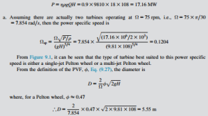
Two (or more) identical turbines are to be installed where the net available head is 108 m and the total flow rate is 18 m3/s. You are required to choose appropriate turbines for the site assum- ing that all the turbines have an efficiency of 90%.
The total power available is
This diameter seems rather large for Pelton wheel turbines and it would be worth looking around to see if suitable alternatives are available.
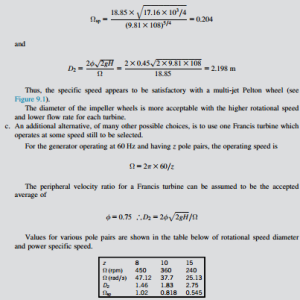
b. Another solution is to use four Pelton turbines operating at 180 rpm (this would require a generator with 20 pole pairs for a supply at 60 Hz) Thus, Ω 5 ð180=30Þ 3 π 5 18:85 rad=s.
It would seem that a good choice of Francis turbine would be the one with eight pole pairs operating at 450 rpm and having an impeller diameter of 1.02 m. The power specific speed suggests that the efficiency would be about 95%.
Related posts:
Incoming search terms:
- all formula of pelton turbine
- calc ul c oeficient cavitatie turbine hidraulice
- cavitations in hydraulic turbine
- defined cavitation in turbine
- Specific speed of turbine cavitation in turbine method to avoid cavitation
- cavitation in turbine
- concept of cavita
- Cavitation in hydraulic turbines
- cavitation in hydraulic turbine and pump
- causes of cavitation in hydraulic turbine
- Problems of cavitation in water turbines
- Professional manufacturer pelton hydro turbine generator mail
- reduce cavitation in turbines
- phenomenon of capitation in water turbine
- Pelton Turbine Generator CNC Machined Francis mail
- Steam Turbine Manufacturers mail
- procedures to avoid cavitation in turbine
- thoma cavitation factor for turbine
- whether cavitation takes place in hydraulic turbines or not
- what is thamos cavitation factor
- what is meant by Cavitation in Hydraulic turbines
- what is caviation in turbine
- turbine cavitation fluid mechanics
- turbine cavation
- thomas cavitation number
- thomas cavitation factor for francis turbine
- npsh formula
- name turbine in which cavitation doesnot occur
- caviation in hydrolic turbine
- cavitatia la turbine hidraulicr
- cavitation in hydraulic turbines occurs
- cavitation in turbines#spf=1
- cavitation occurs at the entry to fransis turbine
- cavitation of hydraulic turbine
- Cavitation of hydro turbine formula
- cavitation of tubine
- define cavitation in turbine
- definition cavitation of hydraulic turbine
- explain the concept of cavitation in turbine
- how cavitation is avoided in turbine
- how to avoid cavitation in turbines
- How to minimize a cavitaion in hydraulic turbines
- hydraulic efficiency of francis turbine formula
- must the cavita factor be greater than the critical cavitation factor in a turbine
- causes of cavitation in hydraulic turbines

