Stationary-Pad Humidifiers
A stationary-pad humidifier contains a stationary evaporator pad over which warm air from a supply duct is drawn by a motor-operated blower or fan. The air picks up moisture as it passes over the pad. The humidified air is then returned to the room or space.
Steam Humidifiers
A steam humidifier (also sometimes called a vaporizer) is used with an electric warm-air furnace or an electric heat pump because neither generates warm air at sufficiently high temperatures to evaporate water. These humidifiers are either gas-fired (natural gas or propane) or operated by electricity. They boil the water and send the steam into the room or rooms.
A typical steam humidifier consists of a metal reservoir to hold the water, a heating element submerged in the reservoir, a float valve, and the control wiring. Water is supplied to the reservoir from the domestic water supply. A float valve regulates the amount of water in the reservoir.
Some steam humidifiers are installed in the return duct (or plenum) or the supply duct (or plenum) of a forced warm-air furnace. When line voltage current is passed through the heating element submerged in the reservoir, it produces steam, which releases its moisture into the warm air passing over it. Other steam humidifiers are independent stand-alone units. Some steam humidifiers boil the water and then cool it before it leaves the unit. Instead of steam, a mist of warm water droplets is sent into the room or rooms.
Bypass Humidifiers
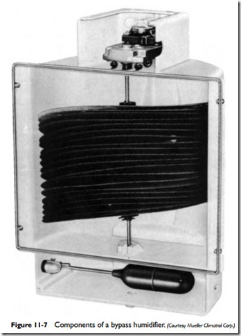
A bypass humidifier (also sometimes called a rotary humidifier, a wet-pad humidifier, or a drum humidifier) consists basically of an evaporator pad (made of sponge or foam fabric) attached to a rotating device such as a drum, disc, wheel, or belt; a float valve; and a small motor. The evaporator pad is first rotated by the motor through a pan of water where it absorbs moisture. Warm air from the supply plenum passes over the rotating pad, causing the moisture to evaporate and humidify the air. The humidified air then mixes with supply air and is ducted into the rooms of the house. Water is supplied to the humidifier from the domestic water supply and is regulated by a float valve. The float valve controls the level of the water in the reservoir.
The principal components of a bypass humidifier are the following:
1. Motor
2. Water tank or reservoir
3. Rotating disc, wheel, drum, or belt
4. Automatic drain valve
5. Float-operated fill valve
6. Overflow line
7. Fill-water connection
8. Drain connection
9. Metal or plastic cabinet
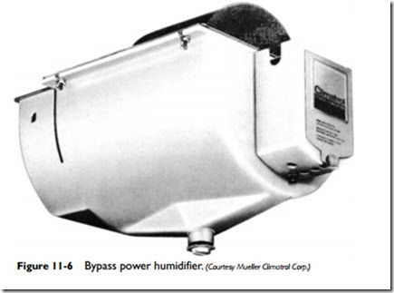
Some of these components are illustrated by the humidifier in Figures 11-6 and 11-7. This humidifier uses bronze wire-mesh discs that rotate at an angle in the reservoir water. The water-level float is isolated in a separate compartment.
A bypass humidifier is commonly located on the furnace supply plenum in a residential heating system where it makes use of the pressure difference between the supply and return air plenums to move the air.
Power Humidifiers
A power humidifier is similar in design to a bypass humidifier except that a fan is added to the unit, the cabinet is larger, and there is no duct connection to the return plenum of the furnace. The fan is used to blow the air across the wet drum, pick up the moisture, and then blow it back into the supply plenum.
Automatic Controls
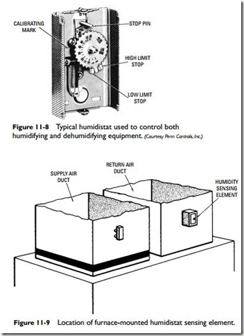
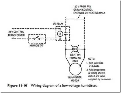
The operation of a humidifier is controlled by a room or furnace- mounted humidistat (see Figure 11-8). The sensing element of the furnace-mounted humidistat should be installed in the return air
duct with the open side down (see Figure 11-9). If the humidifier is installed with a plenum adapter, the sensing element of the humidistat should be mounted above the bypass duct. Never use a furnace- mounted humidistat with a horizontal furnace.
A room humidistat should be mounted on a wall 4 to 5 ft above the floor in a location that has free air circulation of average tem- perature and humidity for the entire space to be controlled. Avoid spots near air ducts or supply air grilles.
Modern programmable humidistats have displays that give the exact humidity level plus the temperature in Fahrenheit or Celsius. The humidity level on the humidistat can be manually set.
Depending on the type of installation, either a low-voltage or line voltage humidistat may be used. Wiring diagrams for both types of control circuits are illustrated in Figures 11-10 and 11-11.


