LADDER DIAGRAMS
Electrical schematics are used to make it simple to trace the circuits of various devices. Some of these can appear complicated, but they are usually very simple when you start at the beginning and wind up at the end. The beginning is one side of the power line and the end is the other side of the line. What happens in between is that a number of switches are used to make sure the device turns on or off when it is supposed to cool, freeze, or heat.
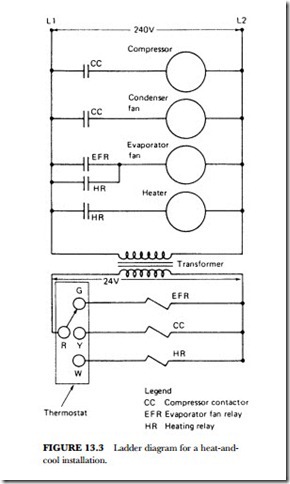
The ladder diagram makes it easier to see how these devices are wired. It consists of two wires drawn parallel and representing the main power source. Along each side you find connections. By simply looking from left to right, you are able to trace the required power for the device. Symbols are used to represent the de- vices. There is usually a legend on the side of the diagram to tell you, for example, that CC means compressor contactor, EFR means evaporator fan relay, and HR means heating relay (see Figure 13.3).
Take a look at the thermostat in Figure 13.3. The location of the switch determines whether the evaporator fan-relay coil, the compressor-contactor coil, or the heating-relay coil is energized. Once the coil of the EFR is energized by having the thermostat turned to make contact with the desired point (G), it closes the points in the relay, and the evaporator fan motor starts to move. This means that the low voltage (24 volts) has energized the relay. The relay energizes and closes the EFR contacts located in the high-voltage (240 volts) circuit. If the thermostat is turned to W or the heating position, it will cause the heating-relay coil to be energized when the thermostat switch closes and demands heat. The energized heating-relay coil causes the HR contacts to close, which in turn places the heating element across the 240-volt line, and it begins to heat up. Note that the HR contacts are in parallel with the evaporator fan-relay contacts. Thus, the evaporator fan will operate when either the heating relay or the evaporator fan relay is energized.
Related posts:
Incoming search terms:
- ladder diagram of air to air heat pump
- pictorial diagram to a ladder diagram
- heating wire ladder schematic
- hvac ladder diagrams
- ladder logic used in hvac systems
- ladder diagram of furnace
- ladder diagram hvac
- ladder diagram for heater
- ladder diagram for furnace
- heating circuits: ladder diagram
- electric fan ladderdiagram
